Designing Holes for 3D Printing: Best Practices for Mass Production
Holes are a fundamental feature in 3D-printed parts, but designing them correctly for mass production requires attention to detail. Poorly designed holes can lead to defects, post-processing challenges, or unreliable fits. In this guide, we’ll explore how to design holes for both side and top surfaces, addressing common issues and sharing techniques to achieve precision and reliability.
Side Holes: Avoiding Deformation
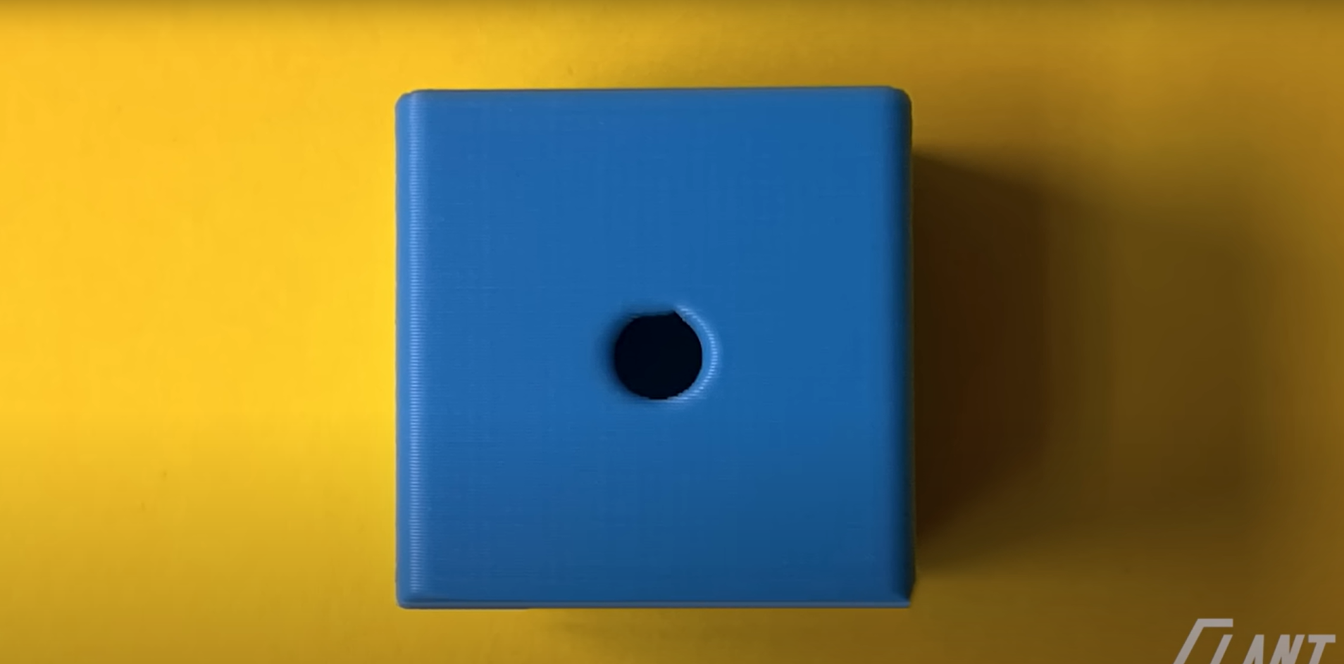
When designing a hole punched through the side of a part, a basic cylindrical hole might seem sufficient. However, this approach often results in defects like rippling around the edges due to the limitations of the tool head and machine motion.
Issue: Sharp corners in a basic hole create stress points, leading to deformation as the tool struggles to maintain precision.
Solution: Add small fillets around the hole’s outer edges. Fillets smooth the tool path, reducing stress and creating a cleaner hole.
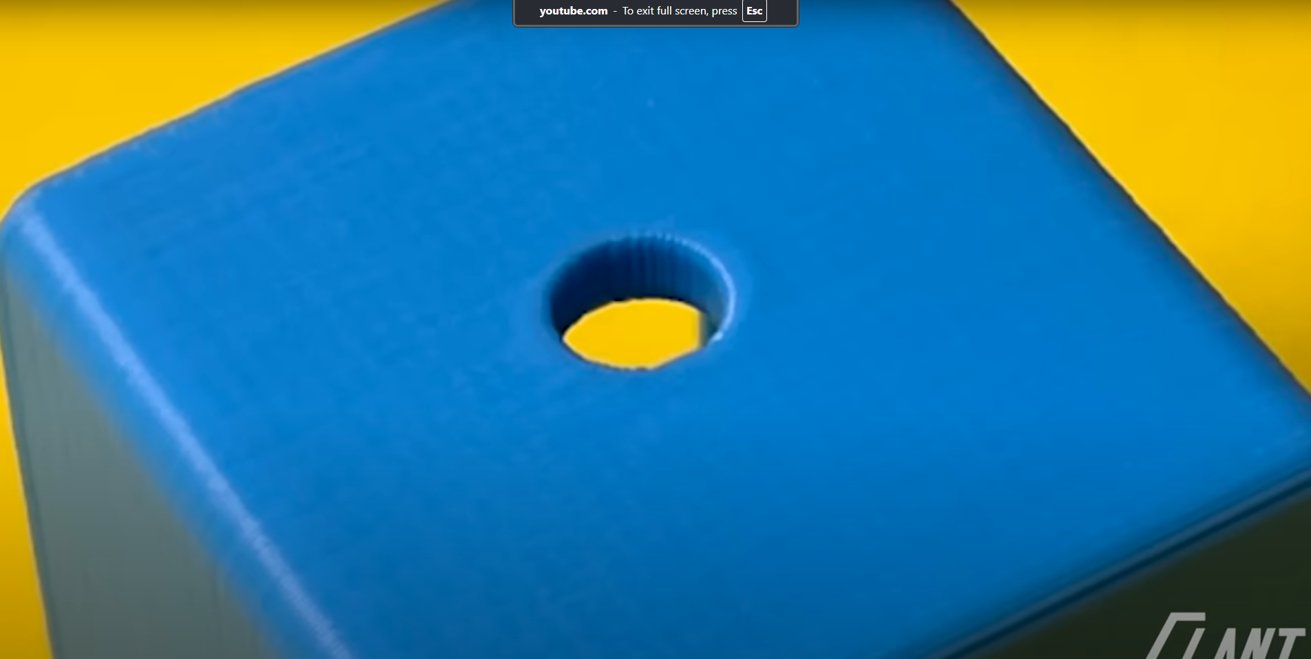
Even with fillets, side holes can sag at the top, especially in applications like electrical enclosures or industrial hardware where precision is critical. Sagging can increase resistance when inserting screws, making assembly difficult.
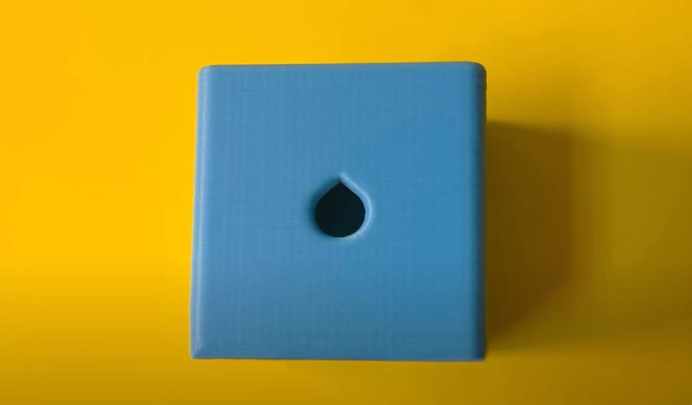
Advanced Solution: Add small points or “teardrop” features at the top of the hole. These points prevent sagging by maintaining the hole’s outer profile, ensuring a consistent fit for screws or dowels. The points eliminate the flat upper surface that causes bridging issues during printing.
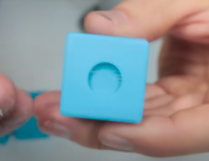
 Top Holes: Managing Unsupported Layers
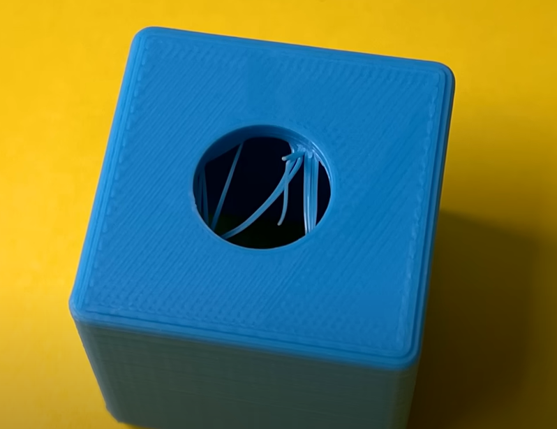
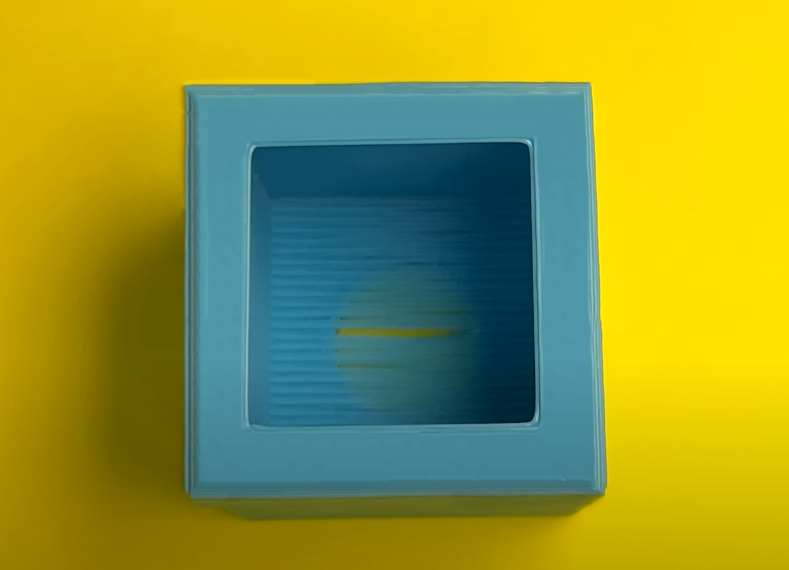
Top holes—those printed perpendicular to the build plate—present unique challenges due to unsupported layers. A basic top hole often results in stranding or drooping filament, as the printer struggles to bridge the gap across the hole.
Issue: Unsupported layers lead to messy, unreliable holes with stray filament that requires extensive post-processing.
Basic Solution: Add support structures beneath the hole. While effective, supports increase post-processing time as they must be removed manually.
Alternative Approach: Use a sacrificial layer to bridge the hole. This reduces some support-related issues but still requires post-processing to remove stranding. For small, non-critical holes, this may suffice, but larger holes risk delamination or weak bottom layers if punched through.
Best Practice: Support larger top holes from underneath to ensure a crisp outer profile. These supports are easier to remove than stranding and maintain the hole’s integrity.