 Mari
Mari
In the realm of digital content creation, the demand for high-resolution textures is paramount, particularly in industries such as film, gaming, and animation where visual fidelity is a top priority. Mari, a powerful 3D texture painting software developed by The Foundry (now part of Foundry), stands out as a leading solution for artists and studios seeking to create intricate and lifelike textures at the highest level of detail.
Introduction to Mari:
Mari represents a paradigm shift in digital texture painting, offering artists unprecedented control and flexibility in crafting high-resolution textures for 3D models. Developed specifically to address the challenges of painting on complex, high-polygonal meshes, Mari provides a robust set of tools and features tailored to the needs of professional texture artists.
Key Features and Capabilities:
- Non-Destructive Workflow: Mari’s non-destructive workflow allows artists to work directly on high-polygonal models without baking textures, preserving every stroke and detail throughout the process.
- High-Resolution Painting: Mari excels at handling massive texture resolutions, enabling artists to paint on models with millions of polygons without compromising performance or quality.
- Layer-Based Painting: Mari’s layer-based painting system provides a familiar and intuitive workflow, allowing artists to organize and manage complex texture projects efficiently.
- Projection Painting: Mari’s powerful projection painting tools enable artists to project textures seamlessly onto models, facilitating the creation of precise and detailed textures across complex surfaces.
- UDIM Support: Mari fully supports the UDIM (U-Dimension) workflow, allowing artists to work with multiple texture tiles seamlessly and efficiently, enabling the creation of ultra-high-resolution textures.
- Customizable Brushes and Tools: Mari offers a wide range of customizable brushes and tools, including brushes for painting, blending, masking, and detailing, empowering artists to achieve their desired effects with precision and control.
- Smart Masks and Selections: Mari’s smart masking and selection tools streamline the texturing process by automatically generating masks based on surface properties such as curvature, occlusion, and directionality.
- Advanced Layer Stack: Mari’s advanced layer stack provides artists with granular control over layer blending modes, masks, and adjustments, facilitating complex texture compositions and effects.
Applications in Production:
Mari has become an industry-standard tool in the production of high-quality digital assets for film, television, gaming, and VR/AR experiences. Its ability to handle massive texture resolutions, complex geometry, and intricate detail makes it indispensable for texture artists working on projects requiring unparalleled visual fidelity.
Discover the Workspace
The Mari workspace consists of a menu bar, a canvas, toolbars, palettes, and a status bar. Palettes are used for working with items such as channels or shaders. They can be either docked in the application or made to float wherever you find them most useful. You can also place toolbars at the top or bottom and on the left- or right-hand side of the canvas.
What it Looks Like
Here is an illustration of the default layout of the Mari workspace that displays with an open project.
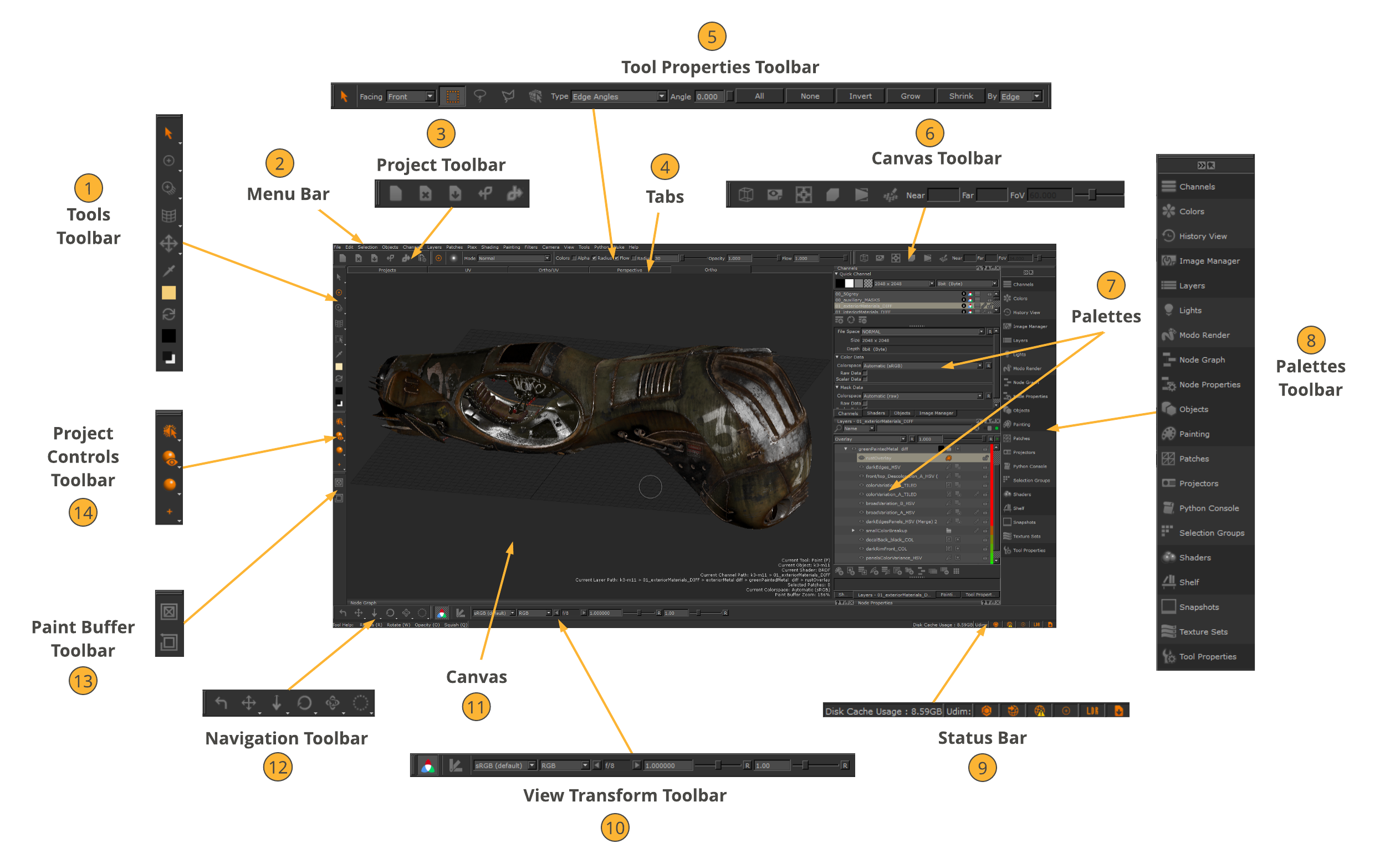 1 Tools Toolbar – The Tools toolbar selects a tool for painting.
2 Menu Bar – The menu bar selects Mari commands, many of which are also available using either shortcut keys or icons.
3 Project Toolbar – The Project toolbar performs common project functions, such as creating, closing, and saving projects.
4 Tabs – The tabs switch between the following views: Projects, UV, Ortho/UV, Perspective, and Ortho.
5 Tool Properties Toolbar – The Tool Properties toolbar displays information about the selected tool.
Note: The illustration above shows the Select tool’s Tool Properties toolbar as the Select tool is selected in the Tools toolbar.
6 Canvas Toolbar – The Canvas toolbar sets the view options for the UV and 3D views.
7 Palettes – The palettes contain controls for viewing and changing different aspects of the geometry on the canvas.
8 Palettes Toolbar – The Palettes toolbar allows quick access to your Mari palettes.
9 Status Bar – The Status bar displays information about the project generally, progress of long operations (such as baking), icons, and basic tool help for the current tool. It also displays how much of your cache disk has been filled.
10 View Transform Toolbar – The View Transform toolbar displays a number of options for managing your monitor’s color space in Mari.
11 Canvas – This is where you view and paint your geometry.
12 Navigation Toolbar – The Navigation toolbar displays a number of options for managing navigation in Mari.
13 Paint Buffer Toolbar – The Paint Buffer toolbar clears all un-baked paint and reset the paint buffer transform.
14 Project Controls Toolbar – The Project Controls toolbar displays a set of four tools:
• Selection – lets you switch between three selection modes.
• Default Shaders – displays one of the four default shaders in the Shaders palette and the last-selected user shader.
• Lighting – lets you change the lighting on the object.
• Paint Buffer Symmetry – displays the four Mirror Painting modes for the Paint Buffer Symmetry functionality.
• Mirror Projection – displays the four Mirror Projecting modes for the Mirror Projection functionality.
Managing Projects
A Mari project stores your work on geometries, and any associated textures. Mari’s Project tab holds all the projects you are working on.
Note: For more detailed information about the New Project dialog,
Creating a New Project
1. Do one of the following: Select from
menu bar
or click on
toolbar
or click on the
Project tab
or type
shortcut key
or from the Project tab, right-click
File > New
New
Ctrl/Cmd+N
New
The New Project dialog displays.
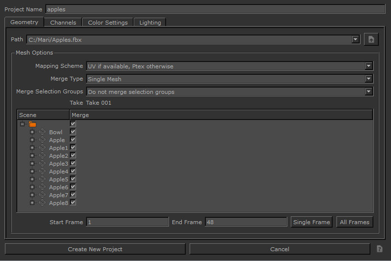
2. Set the Project Name (for you to identify it only – this is not a filename).3. In the Geometry tab, follow these steps:
• Select the geometry file for the project in the Path field. The dropdown lists the last 10 files selected, or you can click to browse to a file.
Various mesh options display in the dialog directly under Path, depending on whether you open an .obj, .ptx, .abc, or .fbx file:
File formats.
Mesh Options
.obj
You can select options for the Mapping Scheme, Selection Groups, and Multiple Geometries Per Object.
.ptx
You can select whether the mesh data in the file represents a single new object or, when there are multiple input files, if the mesh data in each file represents a separate geometry in a single new object by setting the Merge Type field.
For more information on the Mesh options.
.abc and .fbx
You can select options for the Mapping Scheme, Merge Type, and Merge Selection Groups, as well as set the objects that are to be merged in the object hierarchy.
.fbx
You can set the animation Take on project creation/object load. This binds the animation take to the object and this cannot be changed again once the animation take has been selected and loaded.
For more information on the Mesh options.
Note: If you are loading an animated sequence with .obj, .abc, or .fbx file formats, Mesh options displays with the additional options Start Frame, End Frame, Single Frame, and All Frames. These provide the frame range to view either user-defined start and end frames, a single frame, or every frame. A Frame Offset also allows you to specify how the Alembic file is loaded into Mari. This is available for .abc files only.
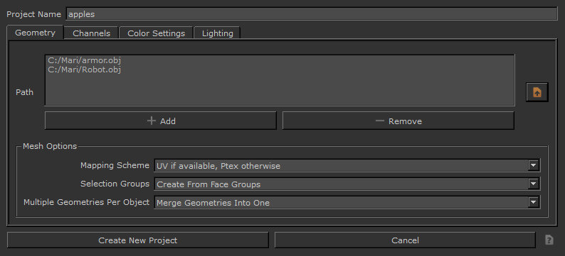
• To create a project from multiple files, browse to a folder and select multiple files from the directory, before clicking Open.
The selected files are all shown in the Path field. These files are stored in the history as a single project under the assigned name.
Note: It’s only possible to create a project from multiple files with .obj and .ptx files. You can only load one .abc or .fbx file when creating a new project.
4. In the Channels tab, set the following channel options: Channel option
Description
Root Path
Select the root path for the project. This is where Mari looks for any existing textures to import as it creates the channels.
Scan
Click Scan to make Mari scan the project’s root path for any existing textures. If any textures exist for your channels, Mari shows a green dot next to the channel. You can select to import these textures.
Category
Selects a Mari channel preset template from the list of available shaders.
The selected channel preset updates with channels.
Template
Select a channel template. Channels templates control the format of the filenames when Mari looks for existing textures on disk.
Prefix
Set a filename prefix for existing texture files, if applicable.
Create
Check the box to create a shader and connect channels to the shader on project creation.
You can right-click to get a dropdown menu allowing you to easily create or import all the channels.
Import
Check the box to import existing textures into the channel after creating it.
You can right-click to get a dropdown menu allowing you to easily import all the channels.
Name
This is the name of the channel to create. Mari sets a default value.
As with the project name, the channel Name is for you to identify it only – when you export you can select a different name.
Size
Set a patch size for the new channel.
ColoSpace
Set the color space in which the colors within your project are interpreted. Either select from the shipped config files or allow Mari to set an Automatic color space.
File Space
Set the file space used when generating vectors.
Fill
Set the Fill option to fill a channel with a specified color, by default.
Depth
Set the Depth.
If you select a different Depth or resolution, file sizes can vary dramatically (for example, a 2k RGB “Byte” texture file is 2MB – whereas a 4k “Float” is 172MB).
Files
Specify the filename template used to pick existing textures to import into the channel. Mari sets a default value, but you can change this, or you can use the button to open a dialog allowing you to manually pick the files.
5. In the Color Settings tab, set your color space options for the project in the following fields:
Tip: If you are just starting out in Mari and aren’t familiar with color spaces, you may want to leave the color space fields at their default.
ColoSpace Option
Description
Color Management Enabled
Enable or disable the Open Color IO color management.
OCIO Config
Select a user-defined config file or shipped Open Color IO config file that handles color space.
Custom OCIO Config
Specify the file path for the custom (non-shipped) config file.
Monitor
Set the default color space, which applies to thumbnails and UI elements. Typically, this should be the same color space as you intend to use for the canvas.
Color Picking
Set the color space for all color pickers, swatches, and image viewers.
8-bit Data
Set the default colors pace for 8-bit channels and reading and writing image files with 8-bit data.
16-bit Data
Set the default color space for 16-bit channels and reading and writing image files with 16-bit data.
8 bits Scalar
Set the default color space for masks, heights, Normals, depths and, generally, any non-color image with 8-bit data.
16/32-bit Float Data
Set the default color space for 16- or 32-bit (float) channels and reading and writing image files with 16- or 32-bit, floating point data.
6. In the Lighting tab, set the following options: Lighting Option
Description
Shader
Select a shading model.
Lighting
Select the lighting on the main mesh.
Active Light Count
Set the number of active directional lights.
Environment Map
Select an environment light.
7. Click the Create New Project button.
Mari renders your selection and displays it on the canvas.
Tip: Depending on the size and complexity of textures, it can take several minutes the first time you load them into a Mari project. Once saved, however, the project should open quickly in future.
Note: Mari checks the model for any errors that might prevent it from processing; for example, touch border edges. A Mesh Sanity Check dialog displays any warnings or errors. (Errors cancel opening the model, but you can continue with warnings.)
Opening Existing Projects
1. Click on the Projects tab.
This shows all the projects you have on your computer.
2. Double-click on the project to open.
Note: On project load, Mari looks for metadata that is over 250MB and discards anything that is over this size. This is intended to strip corrupt and problematic data, and also affects metadata added through the Python API.
Using the Command Line
You can also open Mari and a specific, existing project, as well as archives using the command line. From the Run dialog on your computer, use a command in the format of:
./mari /tmp/testproject.mra
By specifying the project name, UUID, folder path, or project. mri path, you open Mari and the designated project.
The command line can also be used to run scripts that contain a Python call to open a project. From the Run dialog on your computer, use a command in the format of:
./mari example_script.py
The example script should contain the Python call to open a project.
Saving Your Project
Do one of the following:
Select from menu bar
or click on toolbar
or type shortcut key
File > Save
Ctrl/Cmd+S
Tip: Save your project often.
-Note that while your textures remain cached locally, saving does not export them, so export often too!
-If you don’t need to save (no changes since the last save), the toolbar icon is gray.
Using Automatic Project Backup & Restore
Mari has a highly optimized project backup system, which makes it easy to maintain your work and restore archives to a previous state in time.
Each time you save your project, Mari records the changes since your last save. This snapshot is saved in your backup location as defined in File > Settings > Backup Path.
Note: Saves in Mari are incremental and store only the difference since the previous save, which means the backup files are often smaller than a full Mari archive.
Opening Save Points
Save points include the date, time, and machine name and are found through the right-click menu on a project thumbnail.
To see save points and restore the project to a previous one:
1. Open the Projects tab,2. Right-click on a project thumbnail, and select Restore to see a list of save points.3. Roll over the save point to see its details and a thumbnail preview of the project.4. Click the desired save point to restore the project.
To find a save point that isn’t in the current backup location, use Other to open a file browser.
Archiving Your Project
You can archive your Mari projects to store all the projects’ information or to share them with other artists.
To archive your project, do the following:
1. Save and close your project before archiving it by clicking on File > Save, then File > Close.2. In the Projects tab, if your project is not already selected, select your project.3. At the bottom of the application, click Archive or right-click on your project and select Archive.
The Archive dialog opens.
4. Browse to the location where you want to archive your project.5. Click Save.
Your project is archived to the location you selected as an .mra file.
Painting
Read about elements of painting within Mari and the different tools you can use to achieve this. Familiarize yourself with features and functionality, as well as specific workflows you might be interested in. Here are some painting basics to get you started.
Painting in Mari is similar to other standard paint programs. Paint using the various tools, then bake it onto your model. Most tools work on unbaked paint, but one or two also work directly on the baked paint on the surface. Each tool has a set of keys that control how it works. By default, the option keys for the current tool are shown on-screen at the top of the canvas.
Paint Tools
To select a tool, select from your shelves or the Tools toolbar:
Paint tools
- Select
- Transform Selected Objects
- Paint
- Roller
- Blur
- Paint Buffer Eraser
- Vector Paint
- Paint Through
- Gradient
- Clone Stamp
- Warp
- Slurp
- Pinup
- Tow brush.
- Marquee Select
- Transform Paint Buffer
- Zoom Paint Buffer
- Vector Inspector
- Eye Dropper
Painting a Constant Color
1. Click to select the Paint tool.2. Click and drag to paint on the model.
Customizing Your Brush
1. On the Tools toolbar, select a painting tool such as Paint, Blur, Vector Paint, Paint Through, Gradient, and Clone Stamp.2. Open the Shelf palette:
• from the View menu, select Palettes > Shelf, or
• right-click in the toolbar area and select Shelf from the dropdown menu.
The Shelf palette displays.
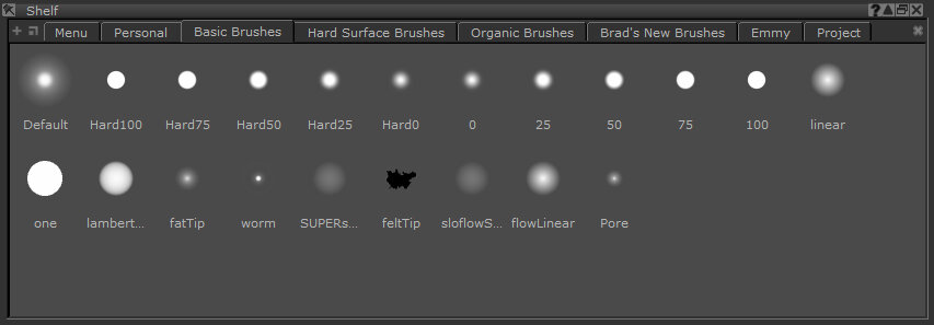
The Shelf palette contains seven shelves:
• Menu – items that you can select from the F9 pie selection control menu.
• Personal – selected items you use regularly.
• Basic Brushes – a set of predefined basic brushes.
• Hard Surface Brushes – a set of predefined hard surface brushes.
• Organic Brushes – a set of predefined organic brushes.
• Brad’s New Brushes – a set of predefined brushes.
• Project – items just for the current project.
3. Click the shelf where your brush is stored.4. Click your brush to select it.5. Open the Tool Properties palette and change the bus properties.
Tip: There are many options for customizing your brush, including setting values for Paint, Pressure, Radius, Rotation, Bitmaps to use, Geometry and Noise. You can test the brush in the scratch pad at the bottom of the Tool Properties palette.
6. To save your customized brush, on the Tool Properties toolbar of your selected painting tool, drag the brush icon to the Shelf palette’s shelf you selected previously.
The modified brush displays in the selected shelf.
“Painting Through” an Image
1. Open the Image Manager palette.2. To load an image, click navigate to and select the image file, and click Open.
A thumbnail of the image displays, along with information about the selected image.
3. In the Tools toolbar, click (the Paint Through tool).
4. Drag and drop the image from the Image Manager to the canvas.
5. Adjust the image size and position
- Resize – Grab and drag its edges or corners or press Ctrl/Cmd+Shift then click and drag.
- Move – Grab the “handle” in the center of the image (or press Shift and click anywhere on the image) and drag.
- Rotate – Click and drag outside the image or press Ctrl/Cmd and drag inside the image.
- Press- Shift when dragging outside the image to rotate in increments.
- Crop Double-click the image in the Image Manager, drag the area you want to crop, and click.
- Change the opacity – In the Tool Properties palette, select Texture > Preview, and change the Preview Alpha (enter a number or drag the slider). Pre-multiply alpha if your image has transparency.
- Reset the image- In the Tool Properties palette, select Texture > Transform > Reset.
6. Paint!
Clone Stamping
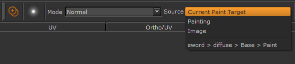
1. select the clone stamping tool.2. Use the Source menu on the toolbar to select where to take the clone source from. You can select the current paint target, an image, or any of the paint layers in the project.
3. If you’re using an image as your clone source, hold down the Ctrl/Cmd key over the image and click to select the clone source point.
Tip: When cloning from a paint layer, you can clone directly from the surface. In this mode, the tool clones the paint from the paint layer surface straight up into the paint buffer directly above that point. This lets you copy the model’s surface into the paint buffer so you can edit it and then re-bake.
To use this mode, hold down Shift+Ctrl when you click to set the origin point. For Mac, this shortcut is Cmd+Ctrl.
4. Paint to clone your selection on the model.
Moving and Warping Paint
To move paint on the model before baking:
1. select the Transform Paint Buffer tool. Left click anywhere on the paint buffer and drag to move the painting around on the model.3. Ctrl/Cmd+left-click and drag to rotate the painting or left-click and drag outside the paint buffer.4. Ctrl/Cmd+Shift+left-click and drag to resize the painting or grab the corners of the paint buffer and drag.
Using this tool…You can…
- Warp – Shift+click and drag to create a warp grid. Click and drag the points around to warp the paint. To increase or decrease the grid resolution, press the up or down arrow keys.
- Slerp – Use the Slerp Mode menu on the toolbar to set the mode (from Pull, Grow, Shrink, or Rotate). Click and drag to apply your effect. Erase distortion by selecting the Eraser mode.
- Pinup – Shift+click to set “pins”. Then click and drag to move the pins. You can use pins to protect parts of the paint that you don’t want affected by the distortion.
Baking Paint onto the Model
To bake paint onto your model:
1. Make sure all patches you want to bake are selected. Do one of the following: Type shortcut key.
Blurring Baked Paint
1. select the blur tool. Left-click and drag to blur paint baked on the surface.
Modeling Requirements
Mari has certain modeling requirements that need to be met in order to use geometry, whether the format of the geometry is an Object, Ptex, Alembic, or FBX file format.
Please bear in mind that Mari allows you to import and paint models with Overlapping UVs, like the one shown below. However, if you paint on regions in the 3D views (orthographic or perspective), which also overlap in 2D UV view, then you may encounter painting artifacts, as Mari is forced to choose which of the conflicting overlapping paint strokes to bake down. To avoid this, you should only apply paint to one of the overlapped regions at a time in the 3D views.
For example, if you paint a face where the left and right halves have been mirrored with overlapping UVs, then you should aim to only paint on one half of the face to avoid paint clashes.
Note: Paint clashing due to overlapping UVs cannot occur in the UV view, so you can always paint your model in that view if you find that your model is particularly tricky to paint in 3D views.
Models to paint in Mari should not have:
• UVs that go over 10 on the U axis – these are ignored.
• Stacked UVs – these cannot be individually selected in UV view. If you do have stacked UVs and want to select an individual UV, you need to select it in either Ortho or Perspective view first, and then switch back to UV view.
• Negative UVs – painting on these is not possible.
Although faces with degenerate UVs (UVs are squashed but their faces remain intact) can be loaded into Mari, they can cause issues in some cases. They do not occupy any space in UV, so it’s impossible to properly paint on such faces. There is also the risk that some shaders may show undesirable lighting effects on faces with degenerate UVs.
Controlling the Way Mari Applies Paint to Your Model
When you paint, Mari saves your painting in a buffer, and then bakes it onto the surface of your model.
About the Paint Buffer
As you paint, Mari saves the painting since your last bake in the paint buffer. Then, when you bake, Mari saves the paint from the buffer, adds it to the surface underneath, and clears the buffer, ready for more paint.
While the paint is still in the buffer, you can make changes to it. If you don’t like what you’ve done, you can erase sections using the Paint Buffer Eraser tool or just blank the entire paint buffer.
Think of the buffer as floating above the canvas. When you bake, Mari adds the paint to the current layer – but until then you can edit the buffer, move the model around underneath it, or switch to another layer and bake the paint there instead. After baking, you can set your preferences to keep the transformations for new paint you add to the buffer, or automatically reset the buffer to the Mari defaults.
Boundaries
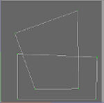
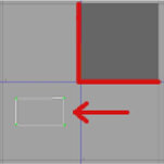
Mari shows the boundaries of the current paint buffer as a white rectangle. By default, the paint buffer is sized slightly larger than the window (that is, it covers everything you can see), so the boundaries are not visible. As you resize it, the boundaries and current details appear.
Paint buffer resized and rotated – note that depth and resolution details display underneath.
Depth and Resolution
The paint buffer has a specific color depth and resolution, which controls the color and resolution of the paint as you apply it (rather than that of the patches that you’re painting onto). For instance:
• If the paint buffer has a color depth of 8-bit (256 colors), then that’s the maximum number of colors that you can use when painting. Even if you’re painting onto a patch with a color depth of 16 or 32 bits (65,536 or 16.7 million colors), the paint you’re applying only has 256 colors.
• If the paint buffer has a resolution of 512×512, the total buffer as it appears on-screen has that resolution. Anything you paint in the buffer is at 512×512. Any patch with a higher resolution still only receives the paint at 512×512.
On the other hand, it’s also true the other way around. If you’re painting onto a 512 x 512 patch with 8-bit color, using a buffer at 1024×1024 and 16-bit color, Mari still saves the patch at 512×512 8-bit. The advantage to using a paint buffer with higher quality than the resulting patches is that you can “overpaint” and use the higher quality texture and color depth to ensure good results. You can use this to help smooth out transitions between colors (preventing stepping), or to ensure that your textures are sharp (that is, at the maximum resolution for the patch).
About Masking
Within the buffer, you can control the paintable area. Mari lets you mask areas on the model. Areas covered by the mask can’t be painted on. It’s the electronic equivalent of putting masking tape over something you don’t want to paint when you’re repainting a wall.
Mari includes the following mask types:
• ambient occlusion mask
• depth mask
• blackface mask
• fractal noise mask
• a configurable edge mask, which masks the areas on the model that are oblique to the current view, and
• a channel mask, where you create a channel for masking, paint in it, and use it to control where you can paint on another channel.
About Blend Modes
When you bake the paint buffer, Mari (by default) adds the contents of the buffer to the surface of the layer below. If you prefer, you can set the buffer to use any one of a number of other blend modes. These correspond to the layer blending modes used in 2D graphics programs such as Photoshop® or GIMP.
The default is for Mari to add the contents of the buffer to the surface. Other blend modes available include varieties of:
• painting the numeric difference between the buffer and the existing surface
• using the contents of the buffer as input for a dodge or burn on the surface
• using the contents of the buffer as input for a hard-light application on the surface.
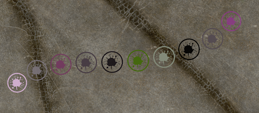
For example, here’s the same paint splash in different blend modes:
Default (over) mode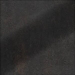 Burn Midrange mode.
Screen mode. Difference mode.
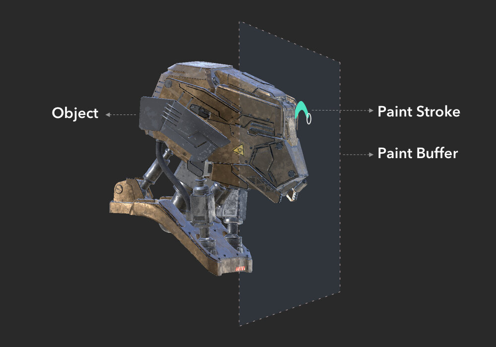
Paint Buffer
Unlike most 3D painting applications, Mari uses a projection-based painting system, which is achieved by using a paint buffer. You can imagine Mari’s paint buffer as a pane of glass located between the artist’s view and the canvas.
The Paint Buffer is controlled by one of three Bake Behaviors, which dictate whether:
• Mari bakes and clears automatically when you change the view (Autobrake and Clear),
• the paint buffer clears automatically once you bake (Clear Only), or
• it needs to be baked and cleared manually (Manual).
Before projecting paint onto objects, you paint into the paint buffer and then bake, which then applies the paint onto the surface of your object.
While the paint is still in the paint buffer, you can make changes to it. If you don’t like what you’ve done, you can erase sections using the Paint Buffer Eraser tool or just clear the entire paint buffer. To adjust where the paint is projected onto the object, you can move the object around underneath the paint buffer or move the paint buffer. Other tools can also be used to affect the paint in the Paint Buffer, refer to:
• Clone Stamping
• Masking What You Can Paint On
• Mirror Projection
• Paint Buffer Symmetry
• Distorting the Paint with Pins
• Pulling, Smudging, Growing, and Shrinking Paint
• Applying a Color Grade as You Clone
• Towing Paint Around
• Warping Paint Using a Grid
• Zoom Paint Buffer tool in the Tools Toolbar
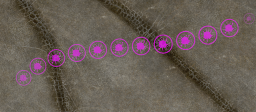
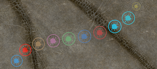
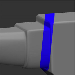
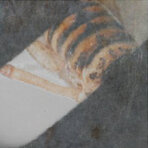
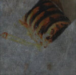
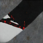
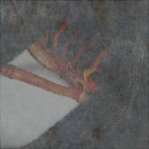
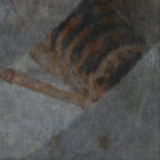
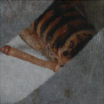
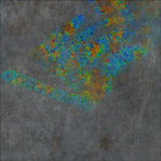
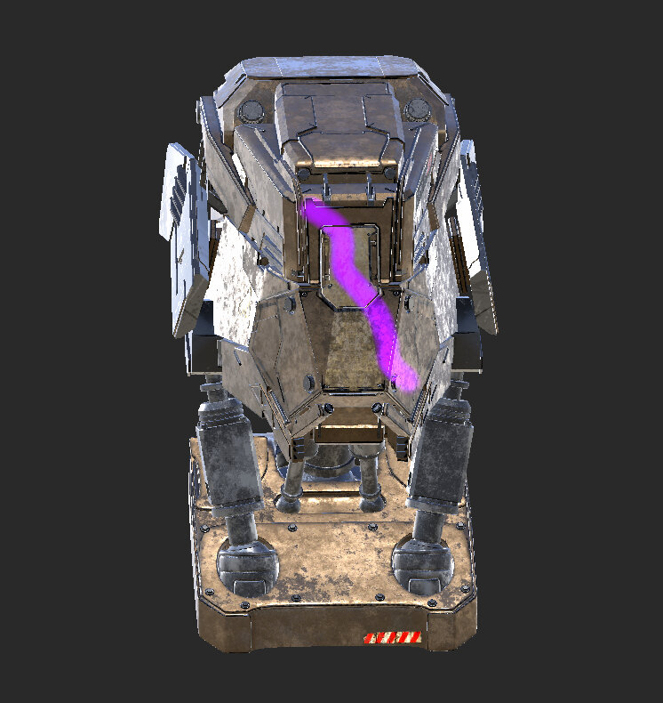
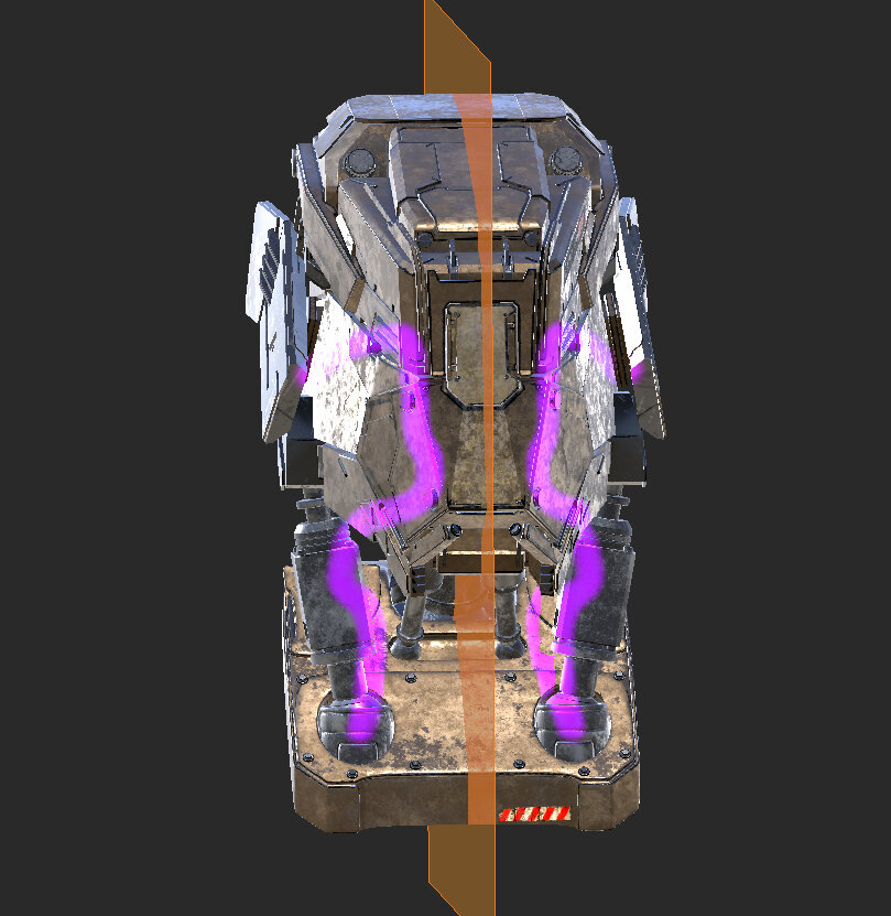
This video shows the workflow using Mari 3. Even though the Mari 4 workspace is different, the workflow remains the same. To have a look at the main UI differences. The images below show you a basic example of how the paint buffer is used in Mari. The Bake Behavior is set to Clear Only meaning that baking paint is done manually, and the paint buffer is cleared automatically.
![]()
Step 1
Paint strokes applied. The paint is saved in the paint buffer.
The paint buffer is moved around (press M key) and the yellow paint moves along with it as it is not baked down yet.
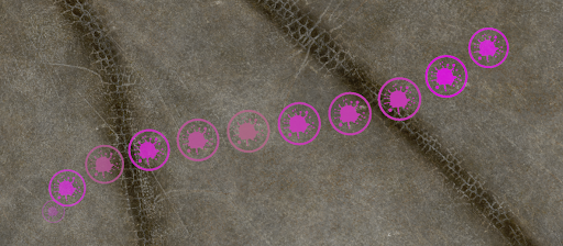
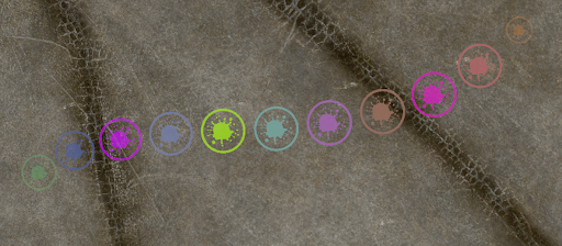
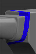
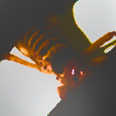
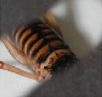
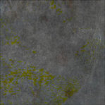
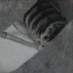
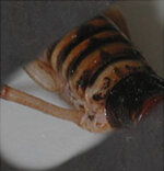
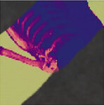
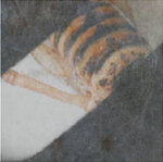
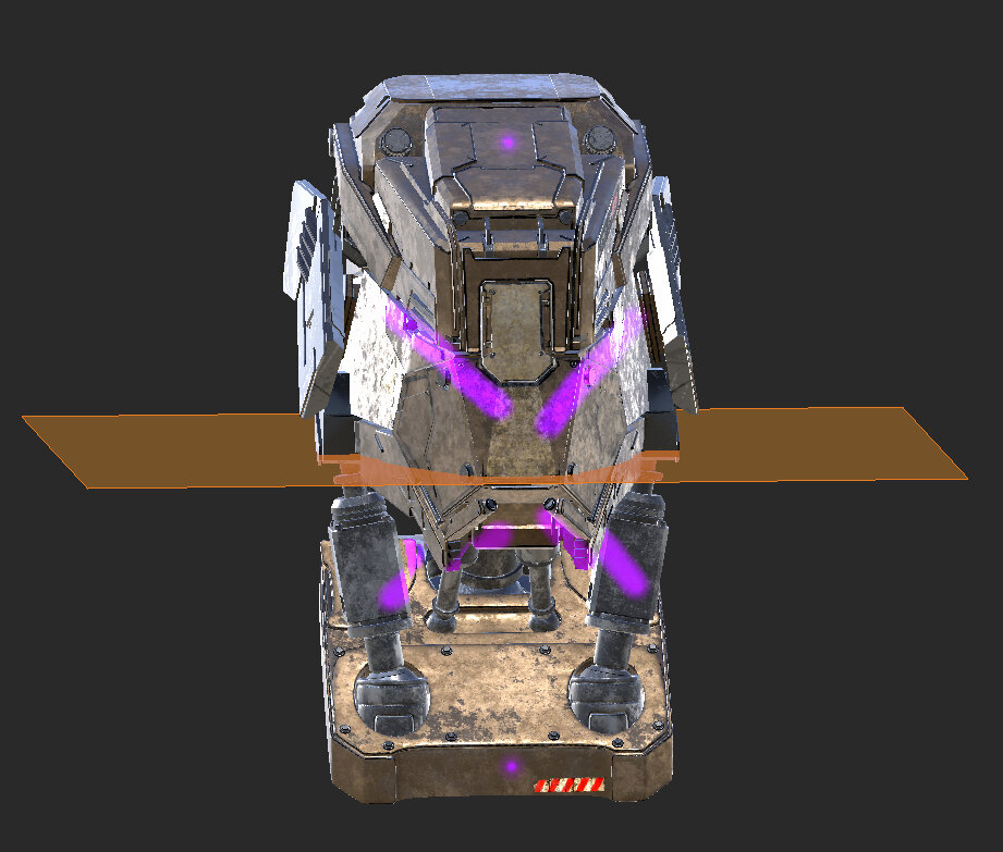
Step 2
The paint buffer is repositioned so that the yellow paint stroke is projected on the object.
Then the yellow paint is baked down onto the object (press B key). The paint is added to the current layer.
The paint buffer is moved around and clear of paint.
![]()
![]()
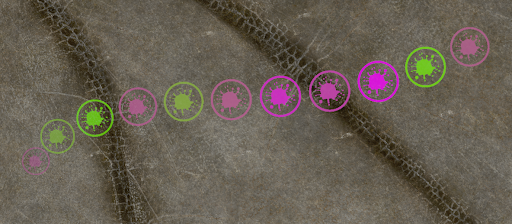
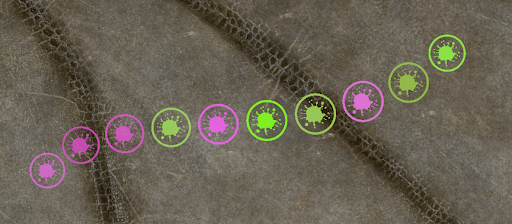
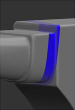
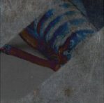
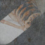
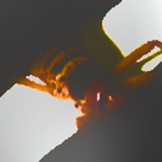
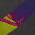
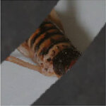
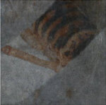
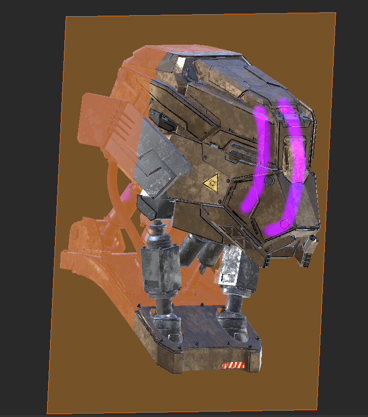
Step 3
An additional blue paint stroke is applied. The blue paint is saved in the paint buffer.
The paint buffer is moved around (press M key) and the blue paint moves along with it as it is not baked down yet, while the yellow paint does not move as it has been baked down onto the object as in step 2.
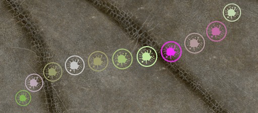
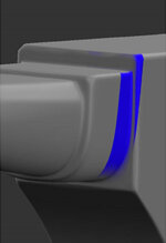
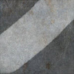
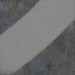
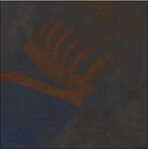
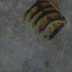
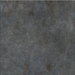
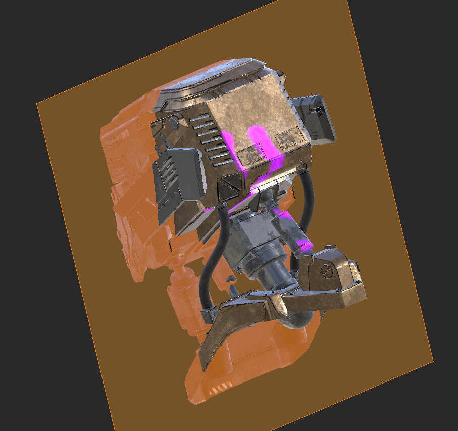
Step 4
The paint buffer is repositioned so that the blue paint stroke is projected on the object.
Then the blue paint is baked down onto the object (press B key). The paint is added to the current layer.
The paint buffer is moved around and clear of paint.
![]()
Configuring the Paint Buffer
1. Start Mari and open your project.2. Open the Painting palette, scroll down, and expand the Paint Buffer section.
Mari displays basic properties of the paint buffer.
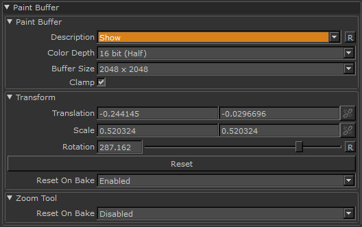
3. Set paint buffer properties:
• Color Depth – controls how many colors the paint buffer can hold. Uncheck this if you want to clone from or paint through a source that has values higher than this range.
• Buffer Size – controls the resolution of the buffer itself.
• Clamp – if checked, Mari restricts the range of the paint buffer to values between 0 and 1.
• Transform (Translation, Scale, and Rotation) – used to Moving or transforming paint buffer in the buffer. But it’s easier to use the Transform Paint Buffer tool.
• Reset on bake – controls whether Mari resets the buffer to its defaults after baking. If enabled, any transformations you’ve made to the paint buffer revert to the defaults. That is, after baking you get a new paint buffer (once again slightly larger than the visible screen). If you want to preserve your transformations after baking, change this to disabled.
Tip: You should always try to set the color depth (and, if possible, buffer size) to at least as high as the highest values for the patches on your model. Mari supports a maximum Buffer Size of 16384 x 16384. However, this setting is not available for all graphics cards. The availability of this setting is determined by the maximum texture size supported by your graphics card.
Please note that increasing the Buffer Size, even when your graphics card supports large textures, can slow Mari’s performance. If you are using patch resolutions higher than 4K, we recommend that you zoom in to the surface when painting, to keep the resolution sharp.
4. Open the Painting palette. This controls how Mari projects paint onto the model when you bake the paint, and mask settings.
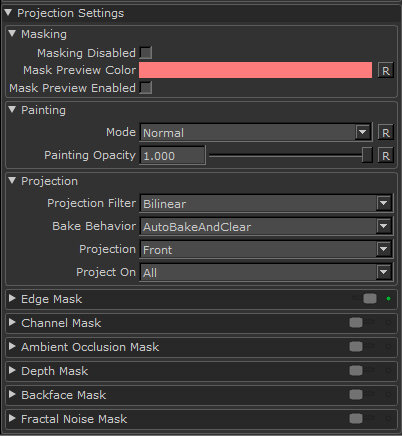
5. Try changing the value for Painting Opacity.
This controls how opaque your paint is in the buffer. At 1.0, you see the paint exactly as you painted it. At 0.5, the paint is half transparent, and at 0 it’s completely transparent.
6. To set properties for baking the buffer, scroll down and expand the Projection section.
The Projection Filter controls how Mari calculates the colors to apply to the surface when you bake the buffer down:
• Bilinear – gives a smooth projection down onto the surface.
• Nearest – gives a hard-edged projection down onto the surface.
7. The Bake Behavior setting controls whether Mari bakes automatically when you change the view, and whether the buffer clears automatically once you bake. The options are:
• Autobrake And Clear – Mari automatically bakes and clears the buffer when you move the model.
• Manual – You have to bake manually; and when you do, the paint stays in the paint buffer until you manually clear it.
• Clear Only – You have to bake manually; and when you do, the paint buffer clears automatically.
Tip: With Manual or Clear Only, you can reposition the model underneath the buffer. This is useful, for example, if you realize that you need to get a better angle on a particular surface on the model.
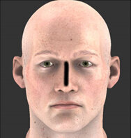
8. The Projection setting lets you set whether Mari projects only onto the Front of the model (as you’re seeing it) or whether paint goes straight Through the model (appearing on the back as well as the front).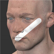 The paint stroke, painted onto the left side of the face.
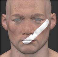 The result, projecting on the Front, rotated so you can see that it’s only appearing in the front of the original view.
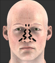
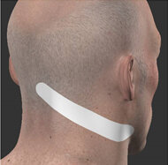 When projecting Through, the paint stroke appears on the back as well as the front.9. In the Project On settings, select whether to project onto only the selected areas, or all patches/objects in the project. For example, if you set Project on to Selected Only, you can only paint on the currently selected areas (whether it’s an area, patch, or object, depending on your selection mode).
This is useful when, for example, painting a face so you don’t have to worry about accidentally overpainting onto the eyes.
Experiment: Paint a couple of example strokes onto your model, so you can see the effects as you work. Try:
Setting Bake Behavior to Manual or Clear Only, and then moving the model around underneath the buffer.
The paint buffer “floats” above the model until you bake it on. For example, you could move it around to get a better angle on a particular surface that you’re painting on, or to paint on a different section of the model.
Using the Zoom Paint Buffer tool to zoom in on your model with the paint buffer locked and without baking the paint down.
Changing channels (through the Channels menu or palette or using the Page Up and Page Down keys). The paint buffer stays in front of the canvas, on the new channel.
Setting Projection to Through. Paint some strokes on your model and bake them. Now rotate the model to see how the paint has “penetrated” it.
Set Project on to Selected. Using the Selection tool, select a patch on your model. Paint a stroke that goes off the edge of the selected patch and bake it. See how the paint that goes off the selection patch disappears when you bake.
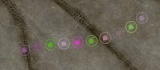
Changing Brush Color Dynamically
In Mari the Color, Hue, Saturation, and Value properties of a brush can be “jittered” on a per stroke, per paint splat or pen pressure basis. Jittering picks random Color, Hue, Saturation, and Value levels from within a given range to alter the brush dynamically as you paint.
Brush color is controlled from the Tool Properties palette under Brush Settings.
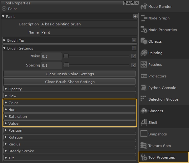
Jittering Color by Stroke, Splat, and Pen Pressure
The Color, Hue, Saturation, and Value slider controls can be configured to jitter by:
- Jitter by Stroke – the Color, Hue, Saturation, and Value property of a brush varies on a stroke-by-stroke basis.
- Jitter by Tip Splat – the Color, Hue, Saturation, and Value property of a brush varies per tip splat of the brush stroke.
- Jitter by Pen Pressure – when enabled, the stroke or tip splat jitters in accordance with how much pressure is applied to the pen of your graphics tablet.
Choosing the Jitter Color
The color range controller allows you to precisely specify how the jittering between the foreground and background color occurs.
The range slider for the color of a brush tip operates from 0.0-1.0, where 1 represents a given background color, and 0 represents a given foreground color.
A brush stroke with no color jitter per tip splat.
A brush stroke with the color jitter per tip splat range set from 0.5 to 1.0.
A brush stroke with the color jitter per tip splat range set from 0.0 to 1.0.
Choosing the Jitter Hue
The hue range controller allows you to precisely specify how the hue of your current selected color will jitter.
Hue shift jitters on a positive or negative basis, with the range slider operating from -1 to +1, where 0 specifies no hue shift jittering.
For example, a negative value on the range slider such as -1 equates to -360 degrees of hue shift. A positive value such as +1 represents +360 degrees of hue shift.
The larger the range between the two values, the more hue shifting occurs in the jitter.
A brush stroke with no hue jitter per tip splat.
A brush stroke with the hue jitter per tip splat range set from -1.0 to 1.0.
A brush stroke with the hue jitter per tip splat range set from -1.0 to 0.0.
Choosing the Jitter Saturation
The saturation jitter slider specifies the range of saturation jittering that occurs in a brush stroke.
The range slider for the saturation of a brush tip operates from 0.0-1.0, where 1 represents a given foreground color, and 0 represents the least saturated version of the given foreground color.
A brush stroke with no saturation jitter per tip splat.
A brush stroke with the saturation jitter per tip splat range set from 0.5 to 1.0.
A brush stroke with the saturation jitter per tip splat range set from 0.0 to 1.0.
Choosing the Jitter Value
The value of the chosen foreground color can also be jittered.
The range slider for the value of a brush tip operates from values of 0.0 – 1.0, where 1 represents a given foreground color, and 0 represents the given foreground color at its lowest value.
A brush stroke with no value jitter per tip splat.
A brush stroke with the value jitter per tip splat range set from 0.5 to 1.0.
A brush stroke with the value jitter per tip splat range set from 0.0 to 1.0.
Erasing Paint
1. To erase a section of paint, click on the Paint Buffer Eraser. Click and drag to erase paint from the paint buffer.
This does not affect the underlying paint baked onto the model, only the paint in the buffer.
Tip: You can edit the brush details for the eraser (brush shape, size, and so on) the same as you would for any other brush.
3. To clear the entire paint buffer, click the Clear the Paint Buffer button.
Mari clears the contents of the paint buffer.
Masking What You Can Paint On
1. In the Painting palette, scroll down to the Projection Settings section.
Masking options are under the Masking, Channel Mask, Ambient Occlusion Mask, Backface Mask, Depth Mask, and Edge Mask sections.
2. If you want to change how masking appears on-screen, change the Mask Preview settings.
• You can temporarily set the Masking Disabled feature by selecting the check box, or pressing Ctrl/Cmd+M. The allows you to see the geometry without any of the current masking channels. This overrides the Mask Preview Enabled feature, even if it is already selected.
• You can set the Mask Preview Color – click the swatch to select a color for the mask from a color picker. The color includes an alpha value, so you can have the mask displayed semi-transparent.
• To display the masking, click Mask Preview Enabled or press , (comma).
When this is on, Mari shows all the masking you have turned on, including channel, edge, depth, and so on.
Additionally, the Luminosity adjustment layer allows you to convert an RGB input to a grayscale output.
When the masking is visible, the ![]() icon displays in the status bar. Clicking this icon, as well as the button in the palette, hides the masking.
icon displays in the status bar. Clicking this icon, as well as the button in the palette, hides the masking.
Other icons show which masking is in use. They are:
![]() for edge masking
for edge masking
![]() for channel masking
for channel masking
![]() for ambient occlusion masking
for ambient occlusion masking
![]() for depth masking
for depth masking
![]() for blackface masking
for blackface masking
![]() for masking disabled
for masking disabled
Edge Masks
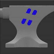
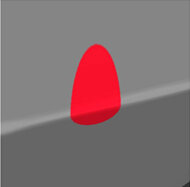
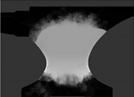
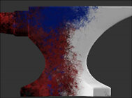
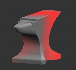
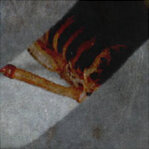
Mari projects paint directly onto the surface of your model based on your view. In other words, it applies paint to what you can see, from the angle you see it. If you paint something you can see, but you’re not facing it directly, there might be falloff, where what you’ve painted has “smeared”. For example, the images below show a spot painted onto a surface of an anvil. From the angle it was painted, it looks like a circle. But if you rotate it, you can see that it “stretched” over the edge.
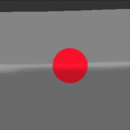
Circle painted front on.
Rotated, you can see the falloff.
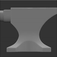
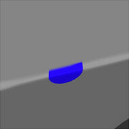
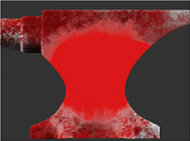
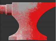
To prevent this from happening, you can configure an edge mask, which masks the falloff area so you can’t paint on it (or so that you can, but the falloff is minimized). The following illustration shows the edge mask tinged in red, and the result of the painting, again baked and rotated.
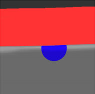
Circle painted front on, with
edge mask.
Rotated, you can see the mask prevented falloff.
Generally, you wouldn’t want such a sharp edge to the paintable area, so Mari lets you specify falloff start and end points to make it fuzzy (unlike the illustration above, where the start and end points are the same). The falloff start is where the masking begins, a proportion of where the projection deviates from directly facing the view. From there, the projection fades out as the mask blends to the falloff end, at which point the projection ends completely (is completely masked) till it hits 90 degrees from facing. You can control how fast the masking falls off.
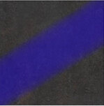
To see how this works, the following illustrations show the result of painting a stripe on the model, like this:
If we bake it, and then rotate to see how much “smeared” into the falloff area, you can see the results of using masks at falloff end/start points of 1.00/0.00 and 0.75/0.25:
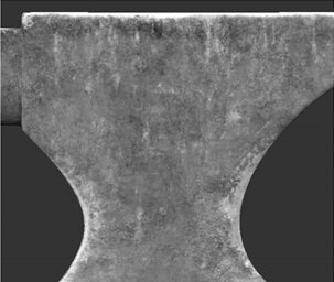
 No mask.
Mask Falloff:
End 1.00, Start 0.00.
Mask Falloff:
End 0.75, Start 0.25.
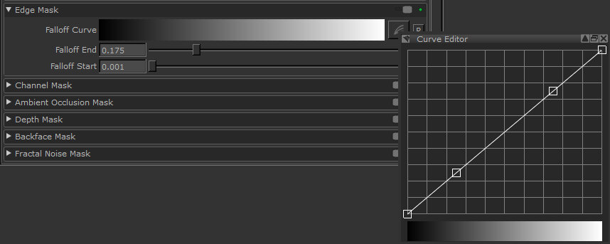
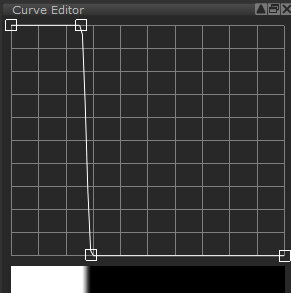
• Falloff Curve – use the curve control to set how the masking falls off between the Start and End points. The start point is at the left of the curve, the end is at the right, and the degree of masking is on the vertical axis.
• Falloff End – where the projection completely fades and the painting is completely masked.
• Falloff Start – is where the masking begins, a proportion of where the projection deviates from directly facing the view, at which point the projection starts gradually fading as the mask’s blends to the falloff end.
Enable the masking by turning on the toggle at the top of the section.
When enabled, the ![]() icon displays in the status bar.
icon displays in the status bar.
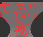
Channel Masks
You can use a channel mask to manually define your own painting mask. You do this by painting into a channel and then using it to control where paint applies to the surface.

Channel mask.
Paint buffer without channel mask.
Paint buffer with channel
mask – see the red masked area
where the white is on the mask.
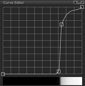
Mari applies the channel mask based on color values on the surface of the channel. This is set up through a curve control:
By default:
• White pixels (value of 1,1,1) are completely masked (totally unpaintable).
• Black pixels (value of 0,0,0) are completely unmasked (totally paintable).
• Other pixels are less masked as their color values approach 0, more masked as they approach 1. For example, 50% gray (0.5,0.5,0.5) creates a mask with 50% opacity.
Mask channel including colored
mask data.
The resulting paint mask.
By altering the curve control, you can set how Mari masks different color values. For example, if you use a displacement map channel as your mask source, you can adjust the mask value to mask out everything except the darkest areas. This gives you a mask that covers everything except the “cracks” in your mask texture.
For example, here’s the result of different settings using this displacement map as a channel mask:
Setting
Result
Notes
This paints into the dark areas – the cracks in the texture.
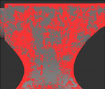
This only unmasks the lightest (that is, the highest) points in the map.
You can also set the contrast for the mask. Mari applies this contrast to the mask channel when producing the final mask.
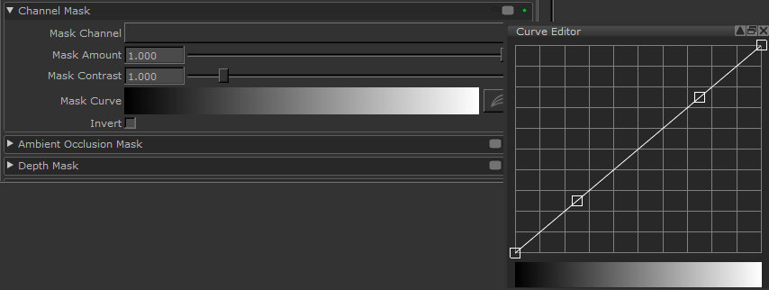
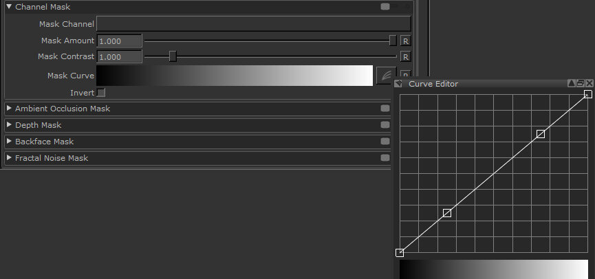
• Mask Channel – lets you select a channel to use as a mask (if you are using a channel mask, you need to create and paint a mask in a channel first).
• Mask Amount – controls the strength of the masked texture coming through, how much unmasked texture to apply. For example, at 0.5, Mari applies the unmasked paint with alpha of 0.5.
• Mask Contrast – controls the contrast used on the mask texture. This controls how sharply defined the mask is – at 1.0, this is just the original mask texture, lower values are fuzzier and higher values are sharper.
• Mask Curve – controls how the input pixel values relate to the degree of masking. The horizontal axis is the darkness of the input pixel (black to the left, white to the right), the vertical axis is the degree of visibility. By default, this is a direct line, where white pixels are totally masked, black pixels are totally unmasked, and 50% gray is 50% masked.
• Invert – applies the mask in reverse. Mari expects masks to be black on white, where the white areas are masked and black is unmasked. However, if you prefer to paint white on black, you can invert the mask input.
Ambient Occlusion Masks
The ambient occlusion mask lets you mask out the parts on your model that are covered by the ambient occlusion. Ambient occlusion is a way of mimicking the soft shadows produced by natural ambient light. The ambient occlusion mask lets you mask out the areas that are shadowed according to this calculation.
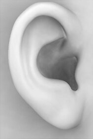
Shader showing the ambient occlusion on this part of the model.
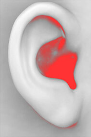
Ambient occlusion mask – the darker the area on the original, the more it’s masked.
If required, you can invert the mask, so as to mask out all the areas not covered by the ambient occlusion.
Before you use an ambient occlusion mask, you must calculate the ambient occlusion for the object.
To use an ambient occlusion mask, set the options under Ambient Occlusion Mask:
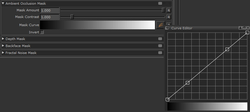
• Mask Amount – is the amount of masking to apply. This is from 0 to 1; higher values mask the areas that are covered by ambient occlusion, while lower values mask everything except the areas that are covered by the occlusion.
• Mask Contrast – controls how sharply defined the mask is. At 1.0, the mask is precisely the same as the ambient occlusion. Higher values mask the occluded areas more, lower values mask them less.
• Mask Curve – controls how the ambient occlusion pixel values relate to the degree of masking. The horizontal axis is the darkness of the occluded pixels (black to the left, white to the right), the vertical axis is the degree of visibility. By default, this is a direct line, where white pixels are totally masked, black pixels are totally unmasked, and 50% gray is 50% masked.
• Invert – if this is selected, the mask data is black on white rather than white on black.
Depth Masks
The depth mask masks out areas on the model depending on how deep they are in the scene (that is, how far from the render camera). This lets you set start and end values and quickly mask out the region between them.
Using depth mask to mask out the far part of the object.
To turn the depth masking on, set the options under Depth Mask:
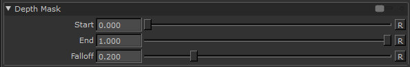
• Start – is how far through the scene the masking begins. This is a proportion of the entire scene in the project, including all objects, lights, and so on.
• End – is how far through the scene the painting is completely masked.
• Falloff – sets how quickly the masking falls off between the start and end points. The interaction between the three settings can be subtle – you may need to play around with different settings to get the effect you want.
Backface Masks
Turning this on simply masks out the backfaces on your model, so you can’t paint on them. There are no other configuration options.
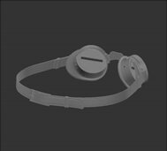
Blackface mask off.
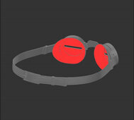
Blackface mask on, masking
the inside of the lens.
To turn the depth mask on, next to Blackface Mask, click to turn the toggle on.
Fractal Noise Masks
The fractal noise mask is a user-controllable masking tool that uses generated noise to mask areas on the surface of an object while painting.
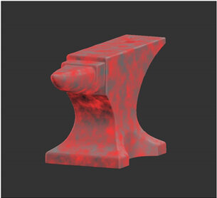
Using fractal noise mask to mask where paint is applied to the surface of the object.
To turn fractal noise masking on, set the options under Fractal Noise Mask:
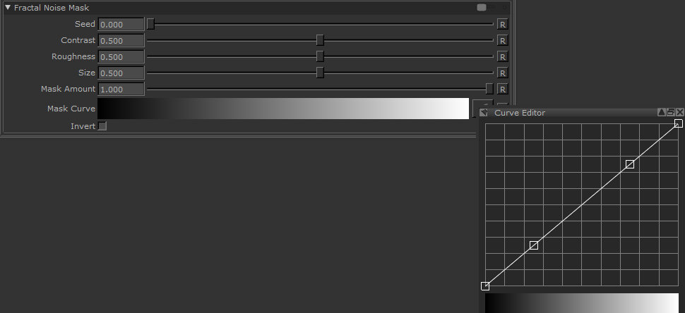
• Seed – changes the pattern of the fractal noise mask by moving the pattern in 3D space.
• Contrast – controls the level of contrast applied to the fractal noise features to derive the mask.
• Roughness – determines the roughness of the fractal noise features.
• Size – Determines the size of the fractal noise features.
• Mask Amount – the amount that the mask affects the paint buffer. 1.0 means that the mask absolutely controls where you can paint; the effects of the mask decrease as the value gets lower.
• Mask Curve – controls how the fractal noise relates to the degree of masking, based on the above fields. This allows you to fine tune the contrast and pattern appearance of the fractal noise mask.
• Invert – if this is selected, the mask data is black on white rather than white on black.
Setting the Paint Blending Mode
1. In the Painting palette, scroll to the Projection Settings > Painting section.
Mari displays the details of the current paint blending mode:
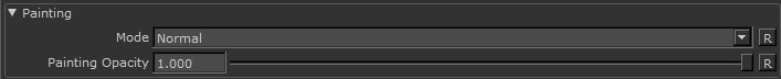
You can also set this in the Tool Properties toolbar.
2. Paint a stroke or two on your model (so you can see the effects of changing the settings).3. Select a paint blending mode from the Painting Mode dropdown.
The paint blending modes available are similar to many other paint packages. If you aren’t familiar with the various modes.
Paint Blending Modes
Mari comes with several paint blending modes. The chart below uses the following example surface and painting to illustrate the effect of applying the different modes:
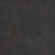
Unpainted surface.
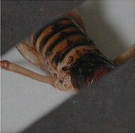
Paint stroke in default blend mode.
There are a number of shortcuts that can help you switch between Previous Blend, Last Blend, or Next Blend modes (among others), as well as resetting the paint blend mode. For a list of available shortcuts,
In the application, these effects are grouped by functional area, for example, all the light modes (hard light, soft light, and so on) are grouped together. This list is alphabetical to make it easier for you to find a description of a particular effect.
Adds the values of the colors in the paint buffer to the values on the layer’s surface.
Add Normal Maps
Blends two RGB-encoded vector layers with the Add input by converting the raw values from the 0.0 to +1.0 colorspace-encoded range to the -1.0 to +1.0 vector range, applying the blend factor to the Over input, adding the values, then normalizing the values before converting it back to the 0.0 to +1.0 colorspace-encoded range.
Burn Highlights – Burns the layer based on the highlights in the paint buffer.
Burn Midrange – Burns the layer based on the middle range (that is, not the lightest or darkest pixels) of the paint buffer.
Burn Shadows – Burns the layer based on the contents of the paint buffer, with darker pixels being burned harder.
Clear – Subtracts the opacity of the paint stroke from the current surface. For example, an 80% opaque stroke leaves a surface with 20% opacity.
![]()
Color – Takes the luminance of the layer, and the color and saturation of the paint buffer.
Color Burn – Burns the layer, using the contents of the paint buffer as input for the burn operation.
Color Dodge – Dodges the layer surface, using the contents of the paint buffer to control the degree of dodging.

Contrast – The destination color moves away from the painted color by contrasting around the painted color. How much it contrasts depends on the alpha.
Darken – Gives each pixel the darker of two possible values: the current layer surface or the contents of the paint buffer (whichever is darker).
Decontrast – The destination color moves towards the painted color by decontrasting around the painted color. How much is decontrasts depends on the alpha.
Difference – Inverts the colors. Mari subtracts the values in the paint buffer from those on the layer surface.
Dodge Highlights – Dodges the layer based on the highlights in the paint buffer.
Dodge Midrange – Dodges the layer based on the middle range (that is, not the lightest or darkest pixels) of the paint buffer.
Dodge Shadows – Dodges the layer based on the contents of the paint buffer, with darker pixels being dodged harder.
Exclusion – Inverts the colors, but with a lowered contrast.
Hard Light – Mimics a harsh spotlight. Makes light areas lighter (using a screen effect), and dark areas darker (using a multiply effect).
Hard Mix – First performs a vivid blend, then thresholds the colors to their extreme values. The result is that the pixels can be one of eight colors – black, white, red, green, blue, cyan, magenta, or yellow.
Hue – Takes the luminance and saturation from the layer pixels, with the hue from the paint buffer.
Inverse Difference – Subtracts the colors in the paint buffer from the layer surface, and then inverts the result.
Invert – Uses the paint buffer as the input to invert the pixels on the base layer.
Lighten – Gives each pixel the lighter of two possible values: the current layer surface or the contents of the paint buffer (whichever is lighter).
Luminance – Takes the hue and saturation of the layer color, and the luminance of the paint buffer. (This is the opposite of the Color blend mode.)
Mix Normal Maps – Blends two RGB-encoded vector layers with the Mix input by converting the raw values from the 0.0 to +1.0 color space-encoded range to the -1.0 to +1.0 vector range, applying the blend factor to the Over input, adding the values, then normalizing the values before converting the value back to the 0.0 to +1.0 color space-encoded range.
Mix Reoriented Normal Maps Blends two RGB-encoded vector layers in a way that preserves the strength and details of both the base and the overlay inputs.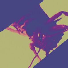
Multiply – Darkens the color. Mari multiplies the layer color by the color in the paint buffer.
Normal – Replace values on the layer’s surface with those from the paint buffer. (Mari’s default mode.)
Nudge Flow Vectors – Changes the paint buffer to tangent vector space. Keeps the vectors flat to the object’s surface in 2D space. The Nudge Flow Vectors mode adds the vectors together to get the blend result, and is best for use with flow maps.
Nudge Normal Vectors – Changes the paint buffer to tangent vector space. Allows the z value to face outward in 3D space, so that vectors face out from the object’s surface anywhere on the model. The Nudge Normal Vectors mode adds the vectors together to get the blend result and is best for use with normal maps.
Overlay – Uses the patterns and colors from the paint buffer but keeps the highlights and shadows from the layer.
Adjustment stacks always use an overlay blend mode.
Paint Flow Vectors – Changes the paint buffer to tangent vector space. Keeps the vectors flat to the object’s surface in 2D space. Unlike Nudge Flow Vectors, the Paint Flow Vectors mode blends between the vectors instead of adding them. This mode is best for use with flow maps.
Paint Normal Vectors – Changes the paint buffer to tangent vector space. Allows the z value to face outward in 3D space, so that vectors can face out from the object’s surface anywhere on the object. Unlike Nudge Normal Vectors, the Paint Normal Vectors mode blends between the vectors instead of adding them. This mode is best for use with normal maps.
Pin Light – For light areas in the paint buffer, replaces pixels on the layer’s surface that are darker than the corresponding pixels in the paint buffer.
For dark areas in the paint buffer, replaces pixels on the layer’s surface that are lighter than the corresponding pixels in the paint buffer.
(Otherwise, leaves the layer surface unchanged.)
Saturation – Takes the luminance and hue of the layer color, with the saturation from the paint buffer.
Scale Vectors – This is most useful with the basic Paint tool, while preferably using grayscale paint. Scale Vectors uses the intensity of color to control the length of the normal in 3D space.

Screen – Lightens the image. Mari divides the color on the surface of the layer by the value of the paint. (This is the opposite of Multiply.)
Soft Light – In dark areas on the layer, burns the paint buffer onto the layer surface. In lighter areas, dodges it on.
Sponge Desaturate – Uses the paint buffer as the input to desaturate the pixels on the base layer.
Vivid Light – In dark areas on the layer, adds the paint buffer with more contrast. In light areas, adds it with less contrast.
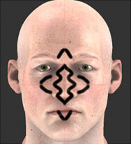
Paint Buffer Symmetry
You can mirror paint strokes in the paint buffer. On the Project Controls toolbar, you can access the Mirror Painting modes. They control whether you want your paint strokes to be mirrored on the paint buffer axis and, if so, how the paint strokes should be mirrored. If you can’t see the Project Controls toolbar, right-click on the toolbar area and choose Project Controls from the dropdown menu.
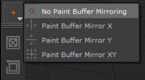
The four Mirror Painting modes are included below, with example paint strokes illustrating the symmetry for each option:
Symmetry Option
Description
Mari’s default paint buffer setting is to have paint buffer symmetry disabled.
Mirroring left and right divides the paint buffer vertically. Paint strokes created on either side of the buffer mirror the same strokes on the other side.
Mirroring top and bottom divides the paint buffer horizontally. Paint strokes created on either side of the buffer mirror the same strokes on the other side.
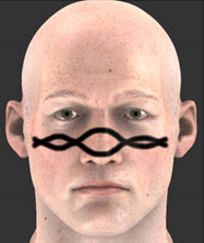
Mirroring four ways divides the paint buffer into quadrants. Paint strokes created in any of the four quadrants mirror in the other three.
Painting in the paint buffer with symmetry enabled only applies to the actual paint strokes. If mirroring is used while in Paint Through mode or while using the Clone Stamp tool, only the paint strokes are mirrored; not the texture being painted through or cloned.
Paint buffer symmetry also mirrors only the paint buffer; it does not project paint onto the opposite side of the geometry.
Mirror Projection
You can mirror the contents of the paint buffer, including any paint strokes and painted-through textures it contains, based on a world space location. Mirror Projection allows symmetrical and asymmetrical painting as you can orientate the mirror plane about the X, Y, and Z axes. You can also use masking options to paint on only one side of the mirror plane.
Note: Mirror projection re-projects the same paint buffer from a symmetrical angle. This means for tools like Clone Stamp, Blur, and TowBrush to work with Mirror Projection, the paint on the model needs to already be symmetrical, or you may find artifacts appear on the mirrored side.
Accessing Mirror Projection Controls
You can access the Mirror Projection controls in two places: the Project Controls toolbar and the Painting palette.
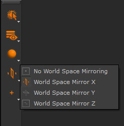
Project Controls Toolbar
On the Project Controls toolbar, you can select the Mirror Projecting modes. These modes set the position of the mirror plane perpendicular to the selected axis. You can also disable Mirror Projection by setting it to No Mirror Projecting.
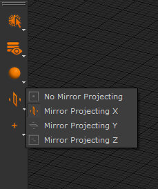
Note: If you can’t see the Project Controls toolbar, right-click on the toolbar area and choose Project Controls from the context menu.
The Mirror Projecting modes are described below, with example paint strokes illustrating the symmetry or asymmetry for each option:
By default, mirror projection is disabled.
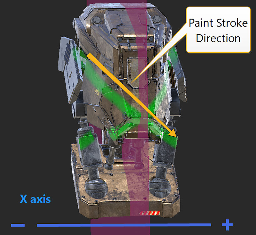
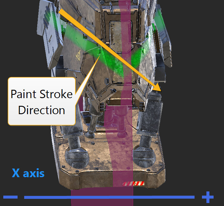
With Mirror Projecting X selected, the mirror line appears vertically. Paint strokes created on either the left or right side of the mirror plane project the same strokes on the other side.
With Mirror Projecting Y selected, the mirror line appears horizontally. Paint strokes created either on top or under the mirror plane project the same strokes on the other side.
With Mirror Projecting Z selected, the mirror line appears vertically intersecting the profile of the asset. Paint strokes created either at the front or back of the mirror plane are projected on the opposite side of the geometry.
Front
 Back
Back
Painting palette
You can also access the Mirror Projection controls in the Painting palette in the Mirror Projection section.
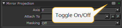
In the Mirror Projection section, you can select one of the Mirror Projecting modes using the Axis dropdown menu. You can also select an object or create a locator to which the mirror plane is attached, using the Attach To dropdown menu and controls. This allows you to move and rotate the mirror plane for different mirroring effects. The Masking dropdown menu let you select the masking modes to paint on only one side of the mirror plane.
Transforming the Mirror Plane
You can transform the mirror plane using locators to align it with objects that are not orientated in line with the origin. The mirror plane attaches to an object or locator, which can then be moved or rotated through 3D space.
Attaching the Mirror Plane to a Locator
1. Navigate to the Painting palette > Mirror Projection section and toggle on Mirror Projection.
2. Select an Axis to choose between vertical (X), horizontal (Y), or vertically front facing (Z) painting.
OR
From the Project Controls toolbar, select one of the Mirror Projecting controls.
3. Select a locator in the Attach To dropdown menu.
OR
Click the + button to create a new locator.
Note: If nothing is selected in the Attach To dropdown, the mirror plane cannot be transformed.
4. Ensure the newly-created locator in the Attach To dropdown menu is selected.5. In the Painting palette > Mirror Projection section, click the P button.
The transform handles appear on the canvas. This allows you to move and rotate the mirror plane.
6. Using the transform handles, drag an arrow or drag a specific axis ring to move and rotate the mirror plane.
Note: Once you have placed the mirror plane, in the Objects palette, make sure to select the required object before painting.
Attaching the Mirror Plane to an Object
1. Navigate to the Painting palette > Mirror Projection section and toggle on Mirror Projection.
2. Select an Axis to choose between vertical (X), horizontal (Y), or vertically front facing (Z) painting.
OR
From the Project Controls toolbar, select one of the Mirror Projecting controls.
3. Select an object in the Attach To dropdown menu.
Note: If nothing is selected in the Attach To dropdown, the mirror plane cannot be transformed.
4. In the Painting palette > Mirror Projection section, click the P button.
The transform handles appear on the canvas. This allows you to move and rotate the object along with the mirror plane.
5. Using the transform handles, drag an arrow or drag a specific axis ring to move and rotate the object along with the mirror plane.
Using Masking Modes
The Mirror Projection masking modes let you paint on only one side of the mirror plane so that your paint strokes can’t cross over the mirror plane line, giving your paint a reflected edge result. You can choose between the following modes:
• Off – This disables the Mirror Projection masking.
• Dynamic – This masks the side (positive or negative) of the mirror plane that is on the opposite side to the current canvas view.
• Positive – This masks the positive side of the current mirror axis, X, Y, or Z, allowing you to paint on the negative side only.
• Negative – This masks the negative side of the current mirror axis, X, Y, or Z, allowing you to paint on the positive side only.
For instance, in the example below, the Mirror Projecting mode is set to Mirror Projecting Y, and a paint stroke is drawn diagonally from top to bottom.
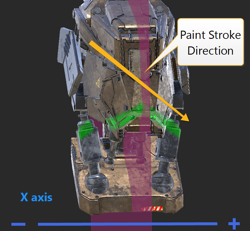 Masking set to OffMasking set to PositiveMasking set to Negative
Changing the Mirror Plane’s Painting Style and Color
To change the color and the painting style of the mirror plane:
1. Right-click on the canvas and select Display Properties.
This opens the Display Properties dialog.
2. In the Mirror Plane section, select the Color, and for the Painting Style select either Mirror Plane or Mirror Line in the dropdown menu.
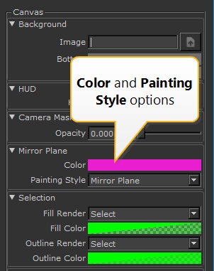
3. Click OK to apply changes.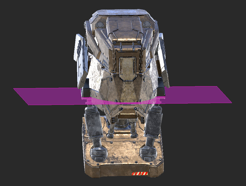
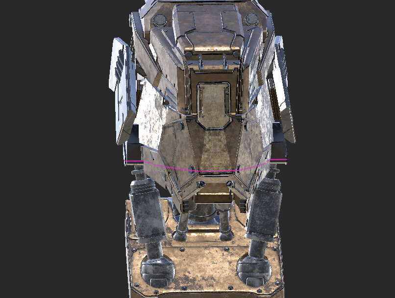 Painting Style set to Mirror Plane Painting Style set to Mirror Line
Paint Continuous, Repeating Textures with the Roller Brush
The Roller Brush tool adds a new painting mode that paints a tileable image following the direction of your brush stroke. For example, you can create seams or decals on a character’s clothing without having to manually line up each tileable texture, one by one, to mimic a brush stroke.
To paint with the Roller Brush:
In the left-hand toolbar, click and hold (the Paint tool). In the drop-down menu that appears, click Roller.
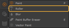
The Roller Brush tool is now available to use.
Adding Images to the Roller Brush
The Roller Brush tool can be used in conjunction with tileable images, allowing you to create seamless details with the stroke of a brush.
To apply an image to the Roller Brush:
- Activate the Roller Brush tool.
- In the Tool Properties window found in the Brush Pallet, expand the Brush Tip menu.
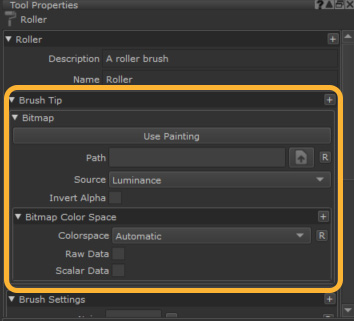
- Click the
 button next to Path field.
 - An explorer window opens.
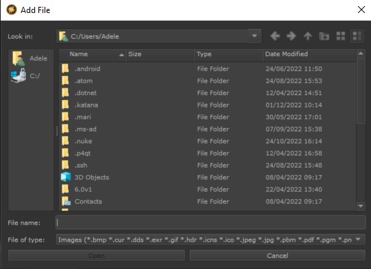
- In the explorer window, select the image you want to use to drive the Roller Brush and click Open.
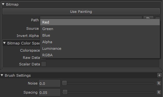
- Depending on how you are planning to use the image assigned to the Roller Brush, you may need to adjust the Source parameter.
- If using an RGB image, you can choose the image’s Red, Green or Blue channels, or RGBA to use all three channels plus an Alpha channel.
- If your image has an Alpha channel you would like to use, choose Alpha.
- If using a black and white image that you would like to use as an Alpha, choose Luminance.
- When Invert Alpha is enabled, any alpha in the brush Source is inverted.
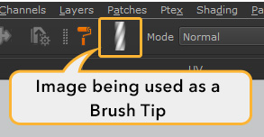
- Once a brush tip is loaded and the source is set, the brush is visible in the top navigation bar, next to the roller brush icon.
Once an image is assigned to the Roller Brush tool, the Roller Brush can be used in the same way as Mari’s default brush. Strokes made by the Roller brush can be manipulated on the paint buffer in the same ways a regular brush stroke would be, and can be baked onto your asset or cleared from the Paint Buffer using the same default commands. For more information on the Paint Buffer, see Paint Buffer.
Roller Brush tool being used with Mirror painting to create even stitches on both sides of the asset.
Curve drawn with the Roller Brush tool being manipulated before baking on the paint buffer with the Warp tool.
Note: When using a brush tip driven by an image, the brush tip will inherit whatever your current foreground color is. To ensure that alpha images and RGBA images are displayed properly, set your foreground color to white.
Roller Brush Settings
There are a number of settings within the Roller Brush Tool Properties that allow you to customize the behavior of the Roller Brush tool. Mari’s Brush Engine dynamics can also be utilized with the Roller Brush, allowing you to create stylized strokes while you paint. For more information on Mari’s dynamic brush engine.
Repeat Direction
Repeat Direction configures Mari to tile your image brush tip Horizontal or Vertical, as well as Vertical Mirrored and Horizontal Mirrored.
Vertical tiles your image vertically along your brush stroke.
Horizontal tiles your image horizontally along your brush stroke.
Vertical Mirrored tiles your image vertically along your brush stroke, while also mirroring every second tip vertically.
Horizontal Mirrored tiles your image horizontally along your brush stroke while also mirroring every second tip horizontally.
Baking in Mari with the Bakery
Baking is an essential part of the texture artist’s toolbox. It enables the display of detail from high-res (high poly) models on low-res models, thereby requiring fewer computational resources to create. You can also streamline creating certain types of materials and effects without having to repaint each time. Let’s say you need an edge wear mask on an object, instead of painting a new mask from scratch each time, you can generate a curvature map as a basis.
In essence, baking refers to the process of converting and flattening dynamically computed 3D geometry into a 2D texture map. The baked texture map is essentially a frozen snapshot of the surface properties, which can then be applied to a lower poly mesh to generate detail within the shader.
High-resolution 3D source data is often too computationally expensive to use when rendering, texturing, or animating. Instead, a 2D texture map can efficiently draw the same details without loss of fidelity.
Example: Imagine the surface of a game character’s skin is cracked and creviced. You can add realism by using ambient occlusion to calculate the shadows that may lie within the cracks. However, calculating these shadows for every frame in a render or animation would require a lot of computational resources. Instead, you can convert this shadow detail into a 2D map known as an Ambient Occlusion map that can be used on the surface of the character to replicate the crack details. The use of a map means that no frame-by-frame recalculation is needed as the map detail is fixed ahead of time.
Capturing Details with Baked Texture Maps
There are many types of mesh maps that can be captured by baking including curvatures, ambient occlusion (AO), and normal maps. This provides a way to collect valuable details such as where shadows lie within ambient lighting conditions, the position of geometry edges, and the thickness of areas within the mesh.
Once generated, the texture map can add surface information and depth to textures and materials, allowing simpler models to display complex visual details without processing heavy geometry. These baked maps can then be used to drive advanced materials, influencing how the textures interact with light and capturing information that may otherwise need to be uniquely painted for each asset.
Mari offers default recipes for the following bake item types:
- Ambient Occlusion – Simulates how an ambient light source affects an asset, especially in crevices and in areas where the asset will cast a shadow upon itself. This creates soft areas of shadow and light.
- Displacement – Captures height information from a high-poly model’s surface details, enabling realistic texture and geometry effects on a lower-poly model.
- Normal – Encodes the angles of the surface Normals from the high-poly model, which gives the low-poly model the appearance of more complex surface detail.
- Position – Records the 3D position of every point on the model’s surface, providing valuable information for directional shading and material effects.
- Thickness – Measures the distance between the top and bottom sides of a surface. This type can be used in subsurface scattering or to simulate various materials such as cloth, skin, or wax.
- Curvature – Highlights the edges and curves of a model by analyzing the bending of its surface. This is useful for highlighting details and can be employed to create edge wear effects in texturing.
The Bakery
Mari provides a dedicated tool for baking mesh maps called the Bakery. Click the Bakery button in the top toolbar to open the Bakery window.

Bakery Workflow Overview
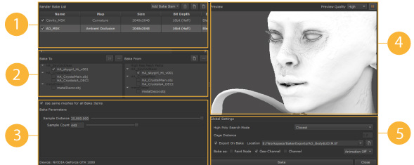
The Bakery offers a simple workflow for baking maps. The numbered steps below correspond to the numbered panels in the UI screenshot above.
- Populate the Render Bake List – Add a list of item types to bake, such as ambient occlusion, and set the texture map’s properties, such as size and bit depth.
- Configure Bake from and Bake To meshes – Choose your high-res mesh to bake from and your lower-res mesh to bake to.
- Adjust the bake item’s Bake Parameters.
- Preview the result for any of the bake items.
- Choose Global Settings – Adjust the general settings and start the bake.
Adding and Editing Bake Item Maps
To add an item to bake, select the texture map recipe from the Add Bake Item dropdown in the top toolbar of the Bakery window.
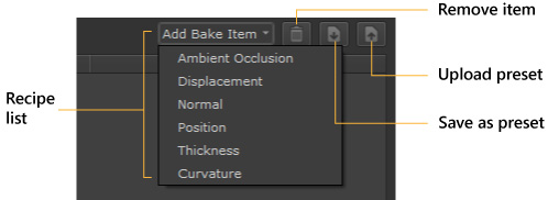
- To remove an item, highlight it in the list and use the trashcan.
- You can also store and upload presets for later use.
See Capturing Details With Baked Texture Maps for more details on each type.
Adding bake recipes populates the Render Bake List.
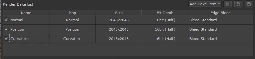
Every item type shares properties that determine how the texture is generated.
Bake Texture Map Properties
For each item in the list, you can edit the following texture properties:
Note: Map is not editable as it is a fixed property that describes the map type.
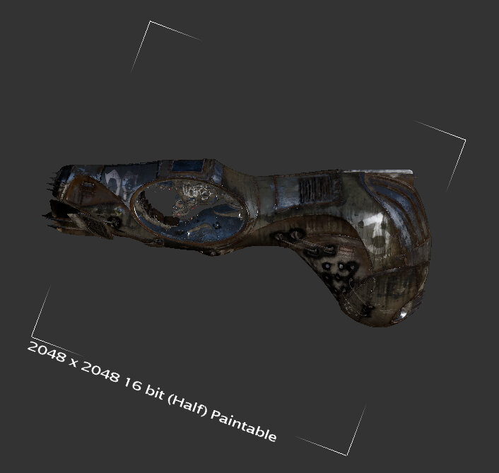
NameName is the map type by default, but you can edit this as needed, particularly if you have multiple maps of the same type. Size Choose the resolution of the texture map. There are eight options ranging from 256×256 to 32768×32768 (32K). Bit Depth Choose from three possible bit depths to define the range of colors in each channel for the texture map:
- 8bit (Byte) – for 256 shades per channel
- 16bit (Half) – for 65,536 shades per channel
- 32bit (Float) – for HDR
Edge Bleed Choose the bleed behavior for the edges around the bake textures.
- Bleed Off – no bleed applied to the output textures.
- Bleed Fast – add bleed but use the fastest and lowest quality algorithm.
- Bleed Standard – add bleed using the slower but better-quality algorithm.
Choosing Meshes for Baking
When baking, you typically take the 3D data from a mesh, which is baked onto a texture that is applied to a different, usually lower poly mesh.
The two meshes are built with equivalent parts so the bake can work smoothly.
The mesh to bake from and the mesh to receive the texture are show in two adjacent panels:
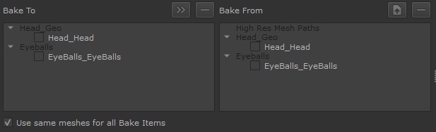
- The Bake To panel displays the lower poly meshes to receive the baked texture.
- The Bake From panel lists the higher poly meshes that provide the data for the bake.
There may be a case when the source and the target mesh are the same model. In certain cases, the mesh may contain enough information to generate a useful map. For example, a simple position map.
The meshes in each panel have a checkbox so that you can select which meshes are involved in the baking process.
A typical workflow would follow these steps:
- By default, the Bake From panel lists the same meshes as your project meshes. You can upload a different high-res mesh using the upload button.
- Select the meshes in the Bake To panel to receive the baked items.
- Propagate the selection from the Bake To meshes to the equivalent meshes in the Bake From panel using the Copy button. This ensures a match between the selections.
You can select individually or clear all selections in each panel using the Clear Selection button.
You also have the option to decide which meshes are used in the bake for each item in the Render Bake List. Toggle Use same meshes for all Bake Items as follows:
- On – The same selection of meshes is used for all the recipes in the list. Select this when you don’t want to customize the mesh selection on a per-item basis.
- Off – Turn off if you want a different mesh selection for each item. This lets you customize the bake per-bake item. For example, when baking an environment, say a kitchen, you many do not want a fruit bowl to cast an occlusive shadow on a tabletop. Simply deselect the fruit bowl in the mesh hierarchy to eliminate it from the bake.
Setting Bake Item Parameters
Each bake item type offers key parameters to customize the look of the texture map. When editing the parameters, you can use the Preview window to check the results. See Previewing the Bake Item.
A position map has no parameters as the source mesh topology derives the position data.
Ambient Occlusion Bake Parameters
Ambient Occlusion (or AO) is a shading technique that adds depth and realism by simulating how diffused light interacts with objects. It introduces soft shadows in areas with limited light exposure, like creases, holes, and closely spaced parts, which can be beneficial in making a material seem more believable.
- Sample Distance Sample Distance is the maximum distance the rays will travel in order to search for occluding surfaces.
- Sample Count Sample Count is the number of rays used to determine shading. More samples mean smoother, more accurate shading but take longer to compute, while fewer samples are faster but can look noisier.
Displacement Map Bake Parameters
Displacement in texture painting is a technique that uses a texture map to change the geometry of a surface. Unlike Normal or Bump maps that only simulate depth, displacement maps physically move the vertices to add genuine depth and detail to the model without increasing the polygon count.
- Bias Bias helps avoid unrealistic shading near object edges. It prevents too-dark areas by adjusting how close an obstruction needs to be to affect the shading. This makes the shading look more natural.
Normal Map Bake Parameters
Normal maps are used to imitate physical depth on a flat surface without modifying its geometry. It fakes recessions and bumps on the surface, creating the illusion of depth and complexity without adding extra resolution to your model.
- Bitangent Bitangent in normal maps is a vector that works with tangent and normal vectors to form a 3D surface coordinate system. This setting is crucial for properly aligning textures and lighting effects. Choose from:
- Per-Pixel Cross Product – Calculates the bitangent for each pixel, providing detailed surface information, making it ideal for high-quality renders but at a higher computational cost.
- Per-Vertex Cross Product – Calculates the bitangent is based on mesh vertices, providing a moderate level of detail and improved performance. This method works well for models that are not primarily detail focused.
- Mesh – Uses the mesh’s own bitangent data, making it ideal for specific requirements where custom bitangent information is embedded in the mesh.
- Invert Y Check this to reverse the direction of the Y-axis in the bitangent vector. Enabling this option helps fix mismatches in normal map orientation between various software or rendering engines. It can help ensure that the textures are displayed correctly.
- Normalization Normalization in baking normal maps ensures all normal vectors are the same uniform length – standardized to a unit vector. This corrects vector lengths for consistent shading, accurate surface detail, and uniform lighting effects. Choose from:
- Per-Pixel – Adjust the length of each normal vector individually for every pixel. This is more computationally expensive but is better at expressing fine detail.
- Per-Vertex – Adjust the length of each normal vector individually for every vertex. This results in lower detail but might be sufficient for simpler models or when computational resources are limited.
- Space Choose the coordinate system to use to interpret the Normals:
- Tangent – Use a local coordinate system at each model’s vertex, making Normals relative to the model’s surface. This allows the normal map to adapt to different shapes and movements. Note: This option is often used in games for its flexibility with dynamic lighting and object movement.
- World – use a fixed, overall coordinate system for the entire scene. This option is ideal for static scenes where objects and lights don’t move.
Thickness Map Bake Parameters
A Thickness map in captures the thickness of a 3D model’s surface. This data is ideal for simulating subsurface scattering and other realistic lighting effects in materials such as skin or marble that have varying densities.
- Sample Distance The sample distance is the depth range used to measure thickness from the model’s surface. This setting determines how deep Mari looks inside the model, affecting the light scattering effects in the final render.
- Sample Count Sample count is the number of samples taken within the defined sample distance to determine the thickness at each point. A higher sample count means more points are evaluated, leading to a more accurate and detailed thickness map. However, higher sample counts are more computationally expensive.
Curvature Map Bake Parameters
A Curvature map creates a gradient where lighter areas represent convex regions of the mesh, and darker areas are more concave. Curvature maps are commonly used as a starting point for creating wear along material edges or for accumulating dirt in mesh cavities.
- Metric Choose a different method (or metric) for calculating and representing the curvature of a surface.
- Tangent Dot – Calculates curvature by measuring the dot product between surface tangents and a fixed direction, emphasizing curvature changes relative to this direction.
- Angle – Measures the angle between surface Normals of adjacent polygons, highlighting sharp edges and distinct changes in surface direction.
- Normal Dot – Uses the dot product between Normals of adjacent surface points to emphasize broader, smoother curvature changes across the surface.
- Multiplier Multiplier adjusts the intensity and contrast of the curvature details to make the effects either more pronounced or subtler. A higher multiplier enhances the highlights and shadows on edges and details for a more dramatic effect. A lower multiplier gives a more subtle enhancement.
- Output Output is the type of curvature information to highlight in the baked map. Choosing the right output depends on which aspects of the model you want to emphasize in your texture.
- Curvature – Generate a map that combines both convex and concave features. The resulting map shows all curvature, highlighting edges and details regardless of whether they curve outward(convex) or inward (concave).
- Convexity – Focus on highlighting the convex parts of the model, which are the areas that curve outward. This is particularly useful for emphasizing raised details, like bumps, ridges, or outward-curved edges.
- Concavity – Focus on highlighting the concave parts, which are the inward-curving areas or indentations. This helps in accentuating recessed details, grooves, or inward-curved edges.
- Sample Offset Sample Offset controls how far the baking process samples geometry from the model’s surface. A larger offset captures broader features, whereas a small offset captures the finer details of the model’s curvature.
- Sample Count Sample Count refers to the number of samples the baking algorithm uses to calculate the curvature. A higher sample count generally leads to a more accurate and smoother curvature map, as the algorithm has more data points to analyze the surface’s curvature. A higher sample count will increase baking time as it is more computationally expensive.
Previewing the Bake Item
The Preview panel in the Bakery lets you visually preview the outcome of your recipes with their current parameters to ensure the final bake output is as expected.
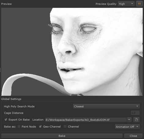
When you adjust the Bake Parameters, the preview auto-updates.
To show a preview click the play button at the top-right of the Bakery.
You can set the Preview Quality to Low, Medium, or High, which in turn affects the preview speed.
Baking and Global Bakery Settings
- High Poly Search Mode When sampling data, choose how to locate the high poly mesh in relation to the low poly mesh.
- Closest – rays are cast perpendicularly from the low-poly mesh to find the nearest points on the high-poly mesh. This is more suited for simpler models and may result in artifacts for complex shapes.
- Cage – this looks for the topmost high-poly mesh by casting rays perpendicularly to a ‘cage’ that encapsulates both meshes. This provides more accuracy when dealing with complex models and when there is a significant difference between the high and low poly meshes.
- Cage Distance the Cage Distance is the distance by which the cage extends outwards from the surface of the low-poly mesh. It’s essential to get this right as too small, and details can be missed. Too large, and this may add artifacts from neighboring geometry. This setting is only active if Cage is selected for the High Poly Search Mode.
- Export On Bake and Location Check Export on Bake if you want to save your baked textures to disk. If checked, choose a Location using the browse button, or from a list of recent locations.
- Bakes as: Choose how to import the baked result into Mari. You can choose from one or more of the following:
- Paint Node – Import the result as a Mari Paint Node.
- Geo-Channel – Import as a Mari Geo-Channel, see Adding Geo-Channels to Objects.
- Channel – Import as a new Mari channel, see Channels.
- Animation If you have an animated object and want to include multiple frames, select whether to include them in the bake:
- Animation Off – Don’t include additional frame data due to animation.
- Animation All – Use all of the animated geometry frames in the bake.
Previewing and Rendering
Projectors
In Mari, projectors store the specific camera details of a particular view – the rotation, zoom, and orientation of the view, plus the current paintable area, the painting mode, and mask settings. Think of this as being like a bookmark for the exact view you currently have in Mari.
You can use a projector to take “snapshots” of your paint buffer, work on them externally, and then project the changes back onto your model. For example, you can use projectors to easily flip back and forth between Mari and Photoshop®, editing a texture in Photoshop®, then projecting it back onto your model and checking it in Mari.
Once you have created a projector, you can use it to project and unproject on and off the image:
• Unproject takes everything visible from the paint buffer and saves it as a file.
• Project reads a file and projects it back onto the model.
Unprojecting takes the surface currently visible in Mari and exports it to a file. This includes everything on the surface, just as it appears onscreen – it’s like taking a snapshot of the model as you can see it right now. So a particular unprojected file could include parts of several meshes. Once you have unprojected to a file, you can edit the file in your paint editor of choice.
When you’re happy with the file, you can then flip back to Mari and project it back onto the view. By restoring the original projector, you can be sure that you’re looking at the exact same view as the snapshot was originally taken from. When you select the projector and click Import (to the buffer) or Project (import and bake), Mari projects the file onto the model in the correct place.
So, once you’ve set up a particular projector, you can quickly flip between Mari and another editor. You only need to set the target and source files for unproject/project once, and then it’s just a click to move back and forth between Mari and your external editor.
To make it easier when you’re working on projects with multiple channels, there is also a batch mode for both unproject and project. This lets you unproject multiple channels at once, or project a set of files back on to multiple channels at the same time.
And to make it even easier to quickly project and unproject, there are Quick modes for both. These project and unproject from the current view, without you having to create a specific projector.
There is also support for unprojecting to a layered .psd file. As with the standard project and unproject features, you can quickly unproject to a layered .psd file without having to create a projector.
In addition, you can also project on to models using .fbx files created by 3rd party software such as Maya. Importing the model, cameras, and textures enables you to quickly create textured models using Mari projectors.
• Render turntables – this exports a single channel, and lets you pick the shader and lighting to use.
• Diagnostic turntables – these export a set of channels, using the default shader and flat lighting, to help you check the current look.
The Projectors palette shows the projectors currently defined for the project.
Exporting and Importing Textures
You can export and import both channels and layers in your project, both in ’flat’ formats, such as .png, and in layered formats, such as .psd or .psb. This is especially useful when exporting multiple layers or channels that you don’t want to take up a lot of space, or when you want to use the final output of a channel in another application.
Importing is how you can pick up an existing set of textures to work on. Similarly, exporting is how your work moves on into the next step in the pipeline:
• Importing loads images into the current channel or layer, or as new channels and layers on your model.
• Exporting saves out the paint on your model as a set of image files (one file per UV patch).
Exporting and importing can be done for both a single channel and layer, as well as multiple channels, layers, even objects in a project. In essence, you can:
• export or import the entire channel (including all layers),
• export or import selected layers, and
• export all channels or objects in a project, or all layers in a layer stack.
Mari supports standard image formats for export and import (such as .tif, .exr, .psd, .png, .jpg, .tga, and .dds). You can find a full list of supported file formats in the import and export dialogs.
When you create a set of new channels, either when creating your project or when using the Channel Presets button, you can import a set of existing textures. See channels for more information.