Seed Studio Lora Wio-E5 mini
INTRODUCTION
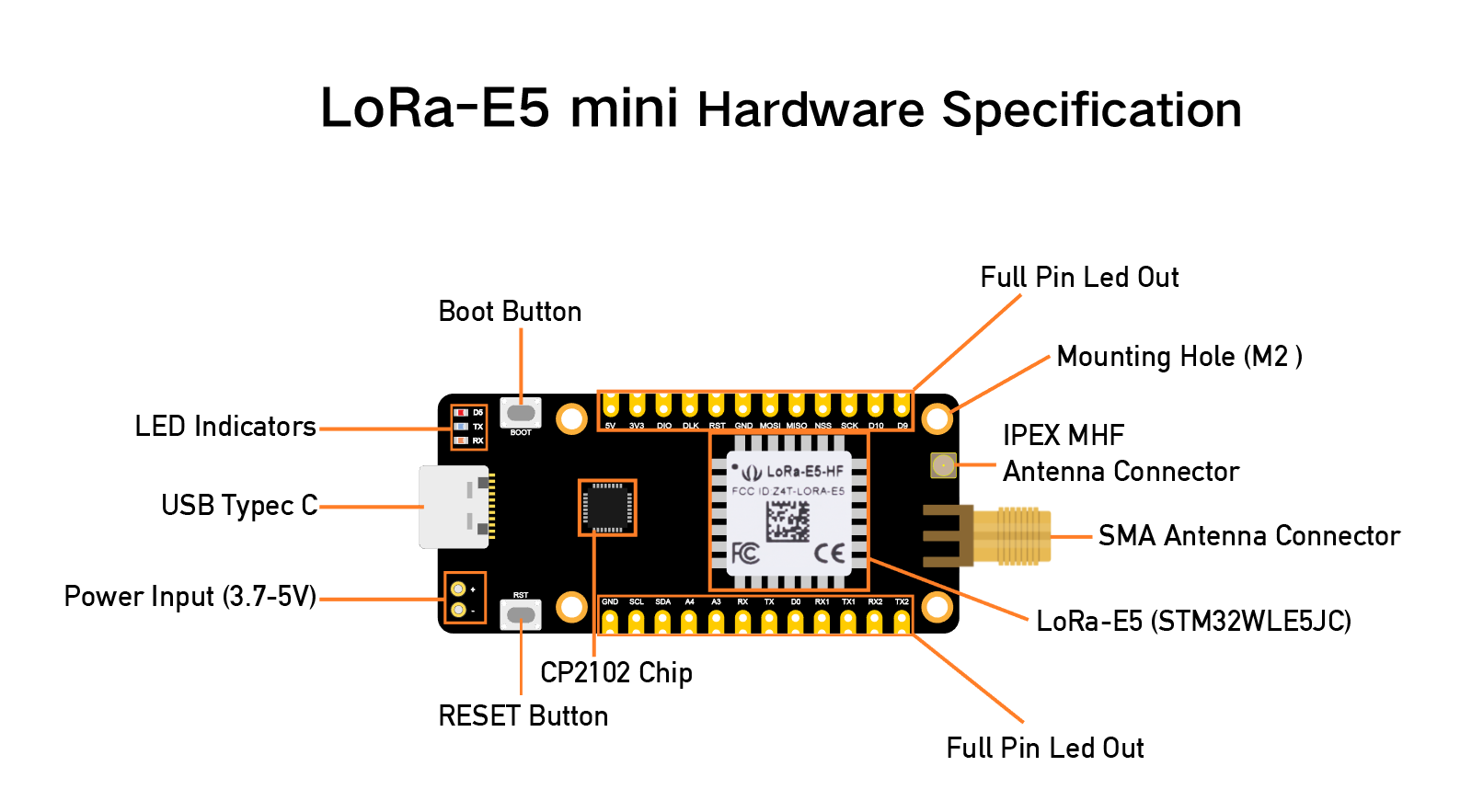
Wio-E5 mini is a compacted-sized development board suitable for the rapid testing and building of small-size prototyping and helps you design your ideal LoRaWAN® wireless IoT device with a long-distance transmission range.
Wio-E5 mini is embedded with Wio-E5 STM32WLE5JC Module, which delivers the world-first combo of LoRa® RF and MCU chip into one single tiny chip and is FCC and CE certified. It is powered by ARM Cortex-M4 core and Semtech SX126X LoRa® chip and supports LoRaWAN® protocol on the worldwide frequency and (G)FSK, BPSK, (G)MSK, and LoRa® modulations.
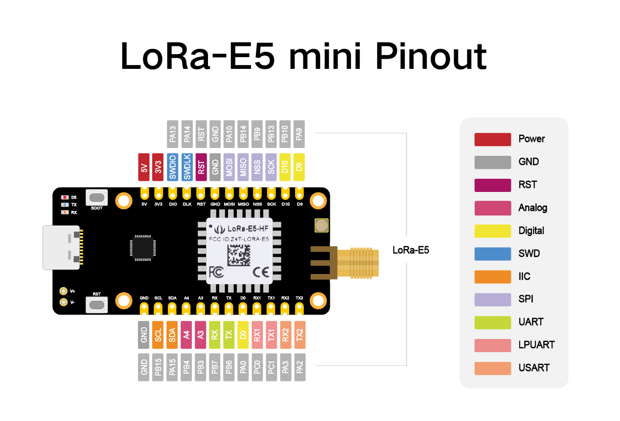
Wio-E5 mini leads out all GPIOs of Wio-E5, including UART, ADC, SPI, IIC, and etc. It contains RESET and BOOT buttons and is use-friendly. Supporting LoRaWAN® protocol, Wio-E5 mini features ultra-long-range transmission and ultra-low power consumption: it can achieve a transmission range of up to 10 km, and the sleep current of Wio-E5 modules on board is as low as 2.1 uA(WOR mode). It is designed with industrial standards with a wide working temperature at -40 ℃ ~ 85℃, high sensitivity between -116.5dBm ~ -136 dBm, and RF output power up to +20.8 dBm at 3.3V.
Other than the Wio-E5 mini, we also provide other choices including the Wio-E5 Development Board carrying more complex interfaces and features to unlock the more powerful performance of the Wio-E5 module. It provides a broader range of access protocols and superabundant types of interfaces. Thus you are able to test and prototype the module rapidly with RS-485, Grove interfaces, and rich GPIOs. (Learn more about Wio-E5 Development Board)
Since Wio-E5 is a LoRaWAN® chip with an MCU, there are three main ways to utilize the Wio-E5 mini:
- Connect Wio-E5 mini to PC and control by AT commands. There is a built-in USB to UART function on board, you could connect the Wio-E5 mini to your PC with a USB type C cable, and use serial communication software to send AT commands and read data from the board.
- Connect Wio-E5 mini to another mainboard via UART and control by AT commands. For example, connect Wio-E5 mini to Seeeduino XIAO and the Expansion Board via UART, and send AT commands and read data from Seeeduino XIAO through Arduino IDE serial monitor.
- User Application Development by using SDK. Develop your own LoRa® development board with MCU function by using STM32Cube Programmer, which is the SDK officially provided by STMicroelectronics.
With all the outstanding features listed above, the Wio-E5 mini will be a superior choice for IoT device development, testing, prototyping, and applications in long-distance, ultra-low power consumption IoT scenarios like smart agriculture, smart office, and smart industry.
If you are unfamiliar with LoRa® and LoRaWAN® technology, please check out this blog LoRa®pedia in detail.
FEATURES
- Full GPIOs led out from the Wio-E5 STM32WLE5JC
- Global LoRaWAN® and LoRa® frequency plan supported
- Long-distance transmission range to 10km (ideal value in open area)
- Mini and compact size, suitable for rapid testing and building small size prototype
- Convenient RESET and BOOT buttons on board
Parameters
Specifications
size
50*23mm
voltage – supply
3.7V – 5V
power – output
up to +20.8 dBm at 3.3V
working frequency
868/915MHz
protocol
LoRaWAN®
sensitivity
-116.5 dBm ~ -136 dBm
interfaces
USB Type C / 2P-2.54mm Hole / 1*12P-2.54mm Header*2 / SMA-K / IPEX
modulation
LoRa®, (G)FSK, (G)MSK, BPSK
working temperature
-40℃ ~ 85℃
current
Wio-E5 module sleep current as low as 2.1uA (WOR mode)
APPLICATIONS
- Wio-E5 module Easy testing
- Rapid small-dimension prototyping of LoRa® devices with Wio-E5
- Any long-distance wireless communication application development
Application Notes
1. Factory AT Firmare
wio-E5 series has a built-in AT command firmware, which supports LoRaWAN® Class A/B/C protocol and a wide frequency plan: EU868/US915/AU915/AS923/KR920/IN865. With this AT command firmware, developers can easily and quickly build their prototype or application.
The AT command firmware contains a bootloader for DFU and the AT application. The “PB13/SPI_SCK/BOOT” pin is used to control Wio-E5 to stay in the bootloader or jump to the AT application. When PB13 is HIGH, the module will jump to AT application after reset, with a default baud rate of 9600. When PB13 is LOW (press the “Boot” button on Wio-E5 mini), the module will stay in the bootloader, and keep transmitting “C” character every 1S at baud rate 115200.
TIP
Factory AT Firmware is programmed with RDP(Read Protection) Level 1, developers need to remove RDP first with STM32Cube Programmer. Note that regression RDP to level 0 will cause a flash memory mass to erase and the Factory AT Firmware can’t be restored again.
The “PB13/SPI_SCK/BOOT” pin on the Wio-E5 module is just a normal GPIO, not the “BOOT0” pin of the MCU. This “PB13/SPI_SCK/BOOT” pin is used in the bootloader of the Factory AT firmware, to decide to jump to APP or stay in bootloader(for DFU). The real “BOOT0” pin doesn’t pinout to the module, so users need to be careful when developing the low-power applications
2. Clock Configuration
- 2.1 HSE
- 32MHz TCXO
- TCXO power supply: PB0-VDD_TCXO
- 2.2 LSE
- 32.768KHz crystal oscillator
3. RF Switch
- Wio-E5 module ONLY transmits through RFO_HP:
- Receive: PA4=1, PA5=0
- Transmit(high output power, SMPS mode): PA4=0, PA5=1
Quick start of AT Commands
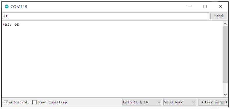
Step 1. Connect Wio-E5 mini to PC via a Type-C cable
Step 2. Open a serial tool(eg. Arudino Serial Monitor), select the right COM port, set baudrate to 9600 and select Both NL & CR
Step 3. Try to send “AT” and you will see the response.
Basic AT Commands
AT+ID // Read all, DevAddr(ABP), DevEui(OTAA), AppEui(OTAA)
AT+ID=DevAddr // Read DevAddr
AT+ID=DevEui // Read DevEui
AT+ID=AppEui // Read AppEui
AT+ID=DevAddr,“devaddr” // Set new DevAddr
AT+ID=DevEui,“deveui” // Set new DevEui
AT+ID=AppEui,“appeui” // Set new AppEui
AT+KEY=APPKEY,“16 bytes length key” // Change application session key
AT+DR=band // Change the Band Plans
AT+DR=SCHEME // Check current band
AT+CH=NUM, 0-7 // Enable channel 0~7
AT+MODE=“mode” // Select work mode: LWOTAA, LWABP or TEST
AT+JOIN // Send JOIN request
AT+MSG=“Data to send” // Use to send string format frame which is no need to be confirmed by the server
AT+CMSG=“Data to send” // Use to send string format frame which must be confirmed by the server
AT+MSGHEX=“xx xx xx xx” // Use to send hex format frame which is no need to be confirmed by the server
AT+CMSGHEX=“xx xx xx xx” // Use to send hex format frame which must be confirmed by the server
Connect and send data to The Things Network
Step 1. Visit The Things Network website and sign up for a new account
Step 2. After logging in, click your profile and select Console
Step 3. Select a cluster to start adding devices and gateways
Step 4. Click Go to applications
Step 5. Click + Add application
Step 6. Fill Application ID and click Create application
Note: Here Application name and Description are not compulsory fields. If Application name is left blank, it will use the same name as Application ID by default
The following is the newly created application
Step 7. Click + Add end device
Step 8. Click Manually, to enter the registration credentials manually
Step 9. Select the Frequency plan according to your region. Also make sure you use the same frequency as the gateway in which you will connect this device to. Select MAC V1.0.2 as the LoRaWAN® version and PHY V1.0.2 REV B as the Regional Parameters version. These settings are according to the LoraWAN® stack of Wio-E5.
Step 10. While the Wio-E5 module is still accessible over the serial console, send the following AT commands on the serial monitor:
AT+ID=DevEui to get your Device EUI
AT+ID=AppEui, to get your App EUI
AT+KEY=APPKEY,”2B7E151628AED2A6ABF7158809CF4F3C” to set the App Key
The output will be as follows:
Tx: AT+ID=DevEui
Rx: +ID: DevEui, 2C:F7:F1:20:24:90:03:63
Tx: AT+ID=AppEui
Rx: +ID: AppEui, 80:00:00:00:00:00:00:07
Tx: AT+KEY=APPKEY,”2B7E151628AED2A6ABF7158809CF4F3C”
Rx: +KEY: APPKEY 2B7E151628AED2A6ABF7158809CF4F3C
Step 11. Copy and paste the above information into DevEUI, AppEUI and AppKey fields. End device ID field will be automatically filled when we fill DevEUI. Finally click Register end device
Step 12. Register your LoRaWAN® Gateway with TTN Console.
Step 13. Type the following AT commmands to connect to TTN.
// If you are using US915
AT+DR=US915
AT+CH=NUM,8-15
// If you are using EU868
AT+DR=EU868
AT+CH=NUM,0-2
AT+MODE=LWOTAA
AT+JOIN
The output on serial monitor will be as follows:
Tx: AT+DR=US915
Rx: +DR: US915
Tx: AT+CH=NUM,8-15
Rx: +CH: NUM, 8-15
Tx: AT+MODE=LWOTAA
Rx: +MODE: LWOTAA
Tx: AT+JOIN
Rx: +JOIN: Start
+JOIN: NORMAL
+JOIN: Network joined
+JOIN: NetID 000013 DevAddr 26:01:5F:66
+JOIN: Done
If you see +JOIN: Network joined on your serial console, that means your device has successfully connected to TTN!
You can also check your device status on the End devices page
Step 14. Type the following AT commands to send data to TTN
// send string “HELLO” to TTN
Tx: AT+MSG=HELLO
Rx: +MSG: Start
+MSG: FPENDING
+MSG: RXWIN2, RSSI -112, SNR -1.0
+MSG: Done
// send hex “00 11 22 33 44”
Tx: AT+MSGHEX=”00 11 22 33 44″
Rx: +MSGHEX: Start
+MSGHEX: Done