Link Budget and Link Margin
- A link budget is the sum of all of the gains and losses from the transmitter, through the medium (aka free space), to the receiver in a telecommunication system. It is a way of quantifying the link performance.
- Transmitter: The radio transmitter value must be specified in dbm, otherwise you do not know its absolute value.
- Gains: Antenna (Unit: dbi)
- Losses: cables, connectors, signal propagating thru the medium (Unit: db)
- When a signal propagates thru the medium, the signal loses strength. This is called the path loss or path attenuation
- A simple link budget equation looks like this:
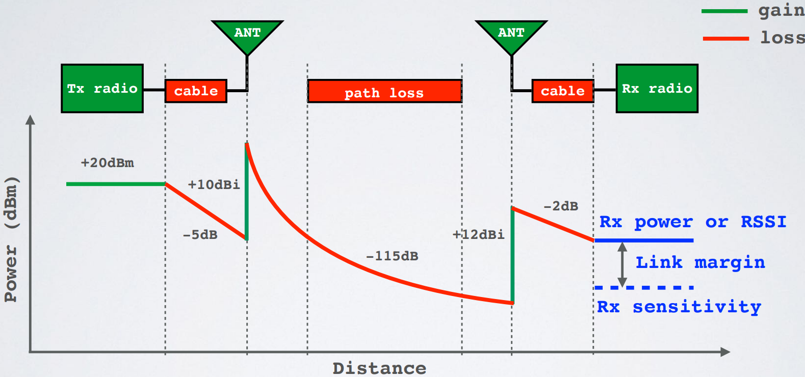
- Received Power = Transmitted Power + Gains − Losses
- For example: Received Power = 20 – 5 + 10 – 115 + 12 – 2 = -80 dBm
- The receiver sensitivity is the lowest power level at which receiver can receive or demodulate the signal. For example:
- Receiver sensitivity = -90 dBm
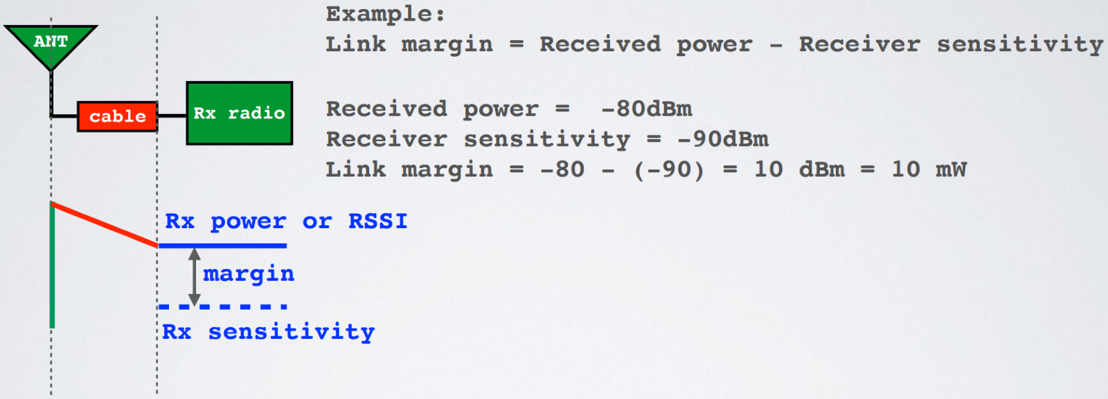
- The link margin is the difference between the received power and receiver sensitivity.
- Link margin = Received power – Receiver sensitivity
- Link margin in dBm
- Received power in dBm
- Receiver sensitivity in dBm
Question:
There are two receivers: Receiver A with receiver sensitivity = -120 dBm Receiver B with receiver sensitivity = -130 dBm Which receiver is better?
Answer:
Receiver B is better because it can demodulate a RF signal at a lower power level.
- If the link margin is too big, or too small, corrective actions can be applied to ensure the system will operate satisfactorily.
- The link margin must be positive (Received Power > Receiver sensitivity) and should be at least a few dB for the receiver to successfully demodulate the signal.
- LoRa receivers are very sensitive and are offering a sensitivity down to -148 dBm [2], due to the use of Chirp Spread Spectrum.
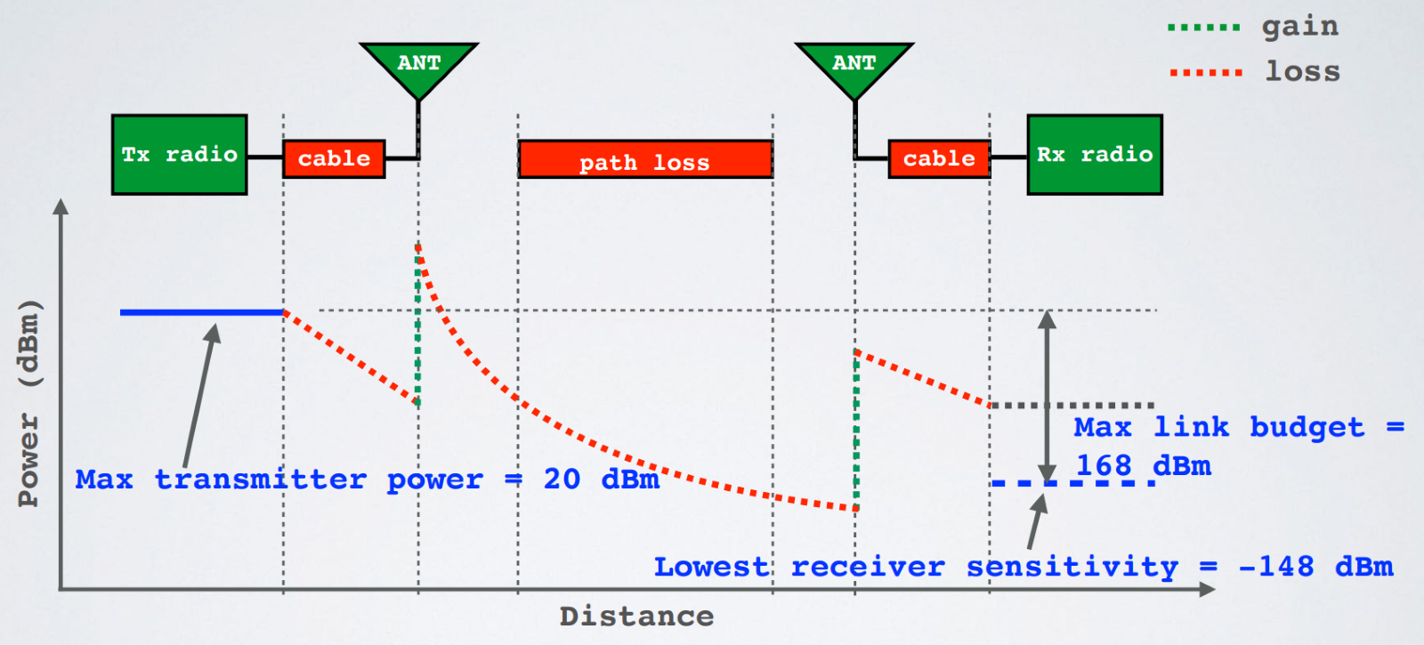
- The maximum link budget can be used as a baseline value to compare one radio to the next.
- Maximum link budget = Maximum transmitter power – Lowest receiver sensitivity
- Maximum link budget in dBm
- Maximum transmitter power in dBm
- Lowest receiver sensitivity in dBm
- For example:
- Max transmitter power = 20 dBm [2], Lowest receiver sensitivity = -148 dBm [2]
- Max link budget = Max transmitter power – Lowest receiver sensitivity
- Max link budget = 20 – (-148) = 168 dBm [2]
EIRP and ERP
EIRP
The Effective Isotropic Radiated Power (EIRP) is the total power radiated by a hypothetical isotropic antenna in a single direction.
ERP
The Effective Radiated Power (ERP) is the total power radiated by an actual antenna relative to a half-wave dipole rather than a theoretical isotropic antenna.
EIRP vs ERP
- EIRP= Tx power (dBm) + antenna gain (dBi) – cable loss (dBm)
- For example: EIRP = 20 + 10 – 5 = 25 dBm
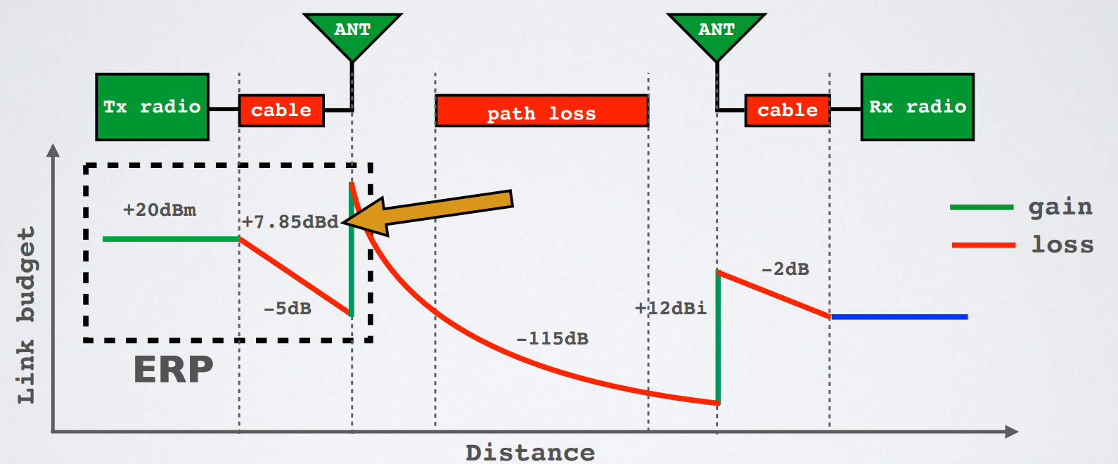
- ERP= Tx power (dBm) + antenna gain (dBd) – cable loss (dBm)
- For example: ERP = 20 + 7.85 – 5 = 22.85 dBm
- Relationship EIRP and ERP: EIRP (dBm) = ERP (dBm) + 2.15
What is the purpose of ERP and EIRP?
- RF transmitting systems must adhere to certain rules set by the regulatory bodies such as FCC or ETSI.
- One of these rules: radio devices must not exceed certain ERP or EIRP values set by these regulatory bodies.
RSSI
- The Received Signal Strength Indication (RSSI) is the received signal power in milliwatts and is measured in dBm. This value can be used as a measurement of how well a receiver can “hear” a signal from a sender
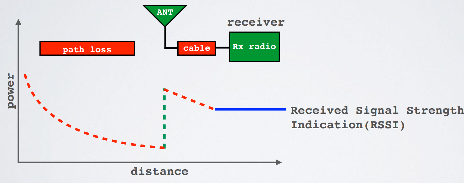
- The RSSI is measured in dBm and is a negative value. The closer to 0 the better the signal is.
- Typical LoRa RSSI values are:
- RSSI minimum = -120 dBm.
- If RSSI=-30dBm: signal is strong.
- If RSSI=-120dBm: signal is weak.
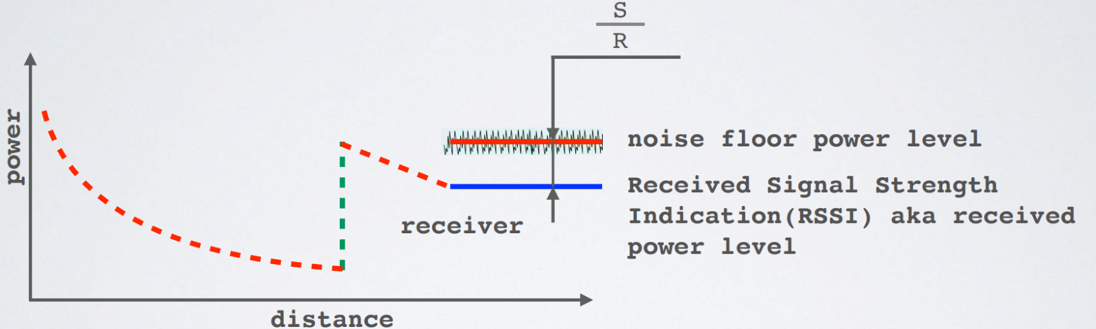
SNR
- Signal-to-Noise Ratio (SNR) is the ratio between the received power signal and the noise floor power level.
- The noise floor is an area of all unwanted interfering signal sources which can corrupt the transmitted signal and therefore re-transmissions will occur
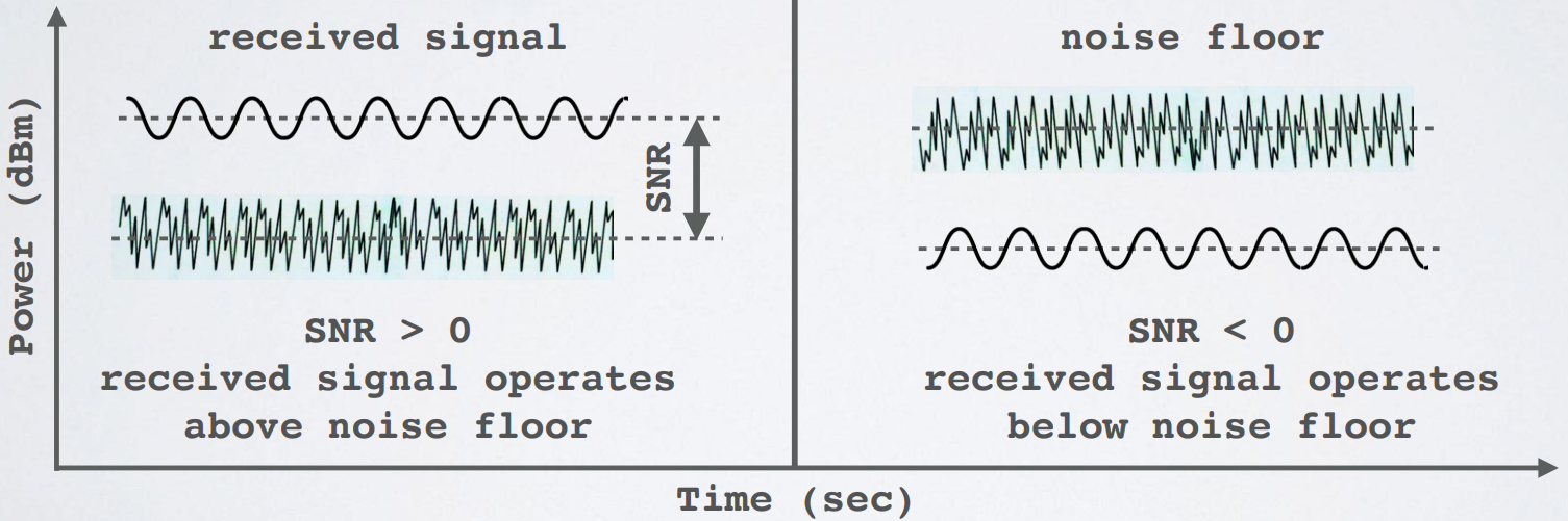
- Normally the noise floor is the physical limit of sensitivity, however LoRa works below the noise level.
- Typical LoRa SNR values are between: -20dB and +10dB A value closer to +10dB means the received signal is less corrupted.
- LoRa can demodulate signals which are -7.5 dB to -20 dB below the noise floor
LoRaWAN Frequencies
- As mentioned before LoRaWAN uses frequencies in the ISM band.
- On The ThingsNetwork (TTN) website you can find the (carrier) frequencies for your country.
- First find the frequency plan which applies to your country
- Frequency Plans | The Things Stack for LoRaWAN (thethingsindustries.com)
- Instead of using the The Things Network (TTN) website, checkout the LoRaWAN Regional Parameters document issued by the LoRa Alliance: LoRaWAN for Developers – LoRa Alliance® (lora-alliance.org)
- This document contains the approved frequency channel plans for various global regions, and follows the established regulatory constraints in those regions.