Mohr’s Circle is a graphical method used in engineering mechanics to determine the normal stress, shear stress, and principal stresses at a given point in a material under loading. It is particularly useful in analyzing plane stress and plane strain conditions in structural and mechanical components.
Key Concepts
1. Stress Components in a Material
A material under loading experiences different stress components:
- Normal Stress (σx, σy): Acts perpendicular to the surface.
- Shear Stress (τxy): Acts parallel to the surface.
2. Principal Stresses (σ1, σ2)
- The maximum and minimum normal stresses at a point.
- No shear stress is present in these directions.
- These stresses define the most critical loading conditions.
3. Maximum Shear Stress (τmax)
- The highest shear stress experienced at a point.
- Important for materials prone to shear failure.
Constructing Mohr’s Circle
- Identify Given Stresses:
- Normal stresses: σx and σy
- Shear stress: τxy
- Determine the Center of the Circle:
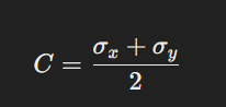
- Calculate the Radius (R) of the Circle:
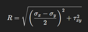
The radius represents the magnitude of maximum shear stress.
- Find Principal Stresses (σ1, σ2):

- Find Maximum Shear Stress (τmax):

- Plot Mohr’s Circle:
- Draw a horizontal axis (Normal Stress, σ) and a vertical axis (Shear Stress, τ).
- Plot two points:
- (σx, τxy)
- (σy, -τxy)
- The center is at C, and the radius R is used to complete the circle.
Applications of Mohr’s Circle
- Structural Engineering: Used to design beams, columns, and pressure vessels.
- Material Science: Helps analyze failure theories like Von Mises and Tresca criteria.
- Mechanical Engineering: Determines stress conditions in machine components like shafts, gears, and frames.
- Aerospace Engineering: Evaluates stress distribution in aircraft structures.