L293D Motor Driver: In-Depth Explanation
The L293D motor driver is a widely used integrated circuit (IC) designed to control the direction and speed of DC motors and stepper motors. It is particularly popular in robotics, automation, and DIY electronics projects due to its ease of use and versatility.
1. Detailed Features of L293D
- Dual H-Bridge Configuration:
- The L293D contains two H-bridge circuits, allowing it to control two DC motors independently or one stepper motor. Each H-bridge can drive a motor in both forward and reverse directions, providing flexibility in motor control.
- Voltage and Current Ratings:
- The L293D can operate with a supply voltage (Vcc2) ranging from 4.5 V to 36 V, making it suitable for a variety of motor types. The continuous current rating is up to 600 mA per channel, with a peak current rating of 1.2 A for short durations, allowing it to handle moderate-sized motors.
- Built-in Protection:
- The IC includes internal flyback diodes that protect against back EMF generated by the motors when they are turned off. This protection is crucial for preventing damage to the driver and the controlling microcontroller.
- Thermal Shutdown:
- The L293D features thermal shutdown protection, which automatically disables the driver if it overheats, preventing damage due to excessive current draw.
- TTL Compatibility:
- The control inputs are TTL-compatible, meaning they can be directly interfaced with microcontrollers like Arduino, Raspberry Pi, and other digital logic devices without the need for additional components.
Operating Modes
The L293D motor driver module can operate in several modes:
Forward Direction:
- To rotate Motor A in one direction, set IN1 to HIGH and IN2 to LOW.
Reverse Direction:
- To rotate Motor A in the opposite direction, set IN1 to LOW and IN2 to HIGH.
Stop:
- To stop Motor A, set both IN1 and IN2 to LOW.
Short Brake:
- To brake Motor A, set both IN1 and IN2 to HIGH.
3. How the L293D Works
The L293D operates by using the H-bridge configuration to control the flow of current through the motor. The H-bridge consists of four switches (transistors) that can be turned on or off to control the direction of the motor:
- Forward Direction:
- To rotate the motor in one direction, you set Input 1 to HIGH and Input 2 to LOW. This configuration turns on the appropriate transistors in the H-bridge, allowing current to flow through the motor in one direction.
- Reverse Direction:
- To reverse the motor direction, you set Input 1 to LOW and Input 2 to HIGH. This configuration turns on the opposite transistors, reversing the current flow through the motor.
- Stop the Motor:
- To stop the motor, both Input 1 and Input 2 should be set to LOW. This configuration turns off all transistors, stopping the current flow.
4. Speed Control Using PWM
The speed of the motor can be controlled using Pulse Width Modulation (PWM) on the Enable pins (Enable 1,2 and Enable 3,4). By varying the duty cycle of the PWM signal, you can adjust the average voltage supplied to the motor, thus controlling its speed.
- PWM Signal:
- A PWM signal consists of a series of on/off pulses. The ratio of the time the signal is HIGH (on) to the time it is LOW (off) is called the duty cycle. A higher duty cycle means more power is delivered to the motor, resulting in higher speed.
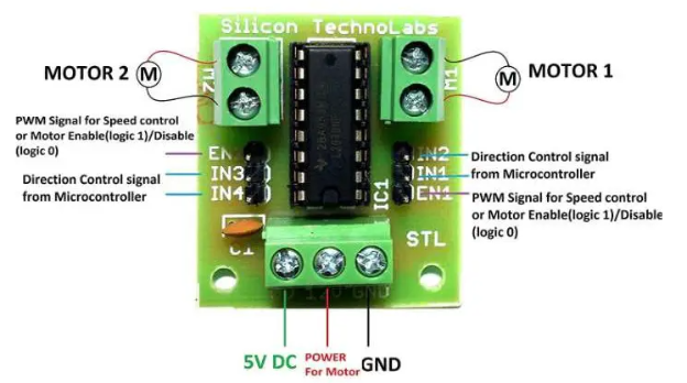
5.Pinout of L293D motor driver module
6. Example Code for Arduino
#define ENA 9 // Enable pin for Motor A
#define IN1 8 // Input pin 1 for Motor A
#define IN2 7 // Input pin 2 for Motor A
void setup() {
pinMode(ENA, OUTPUT);
pinMode(IN1, OUTPUT);
pinMode(IN2, OUTPUT);
}
void loop() {
// Rotate Motor A in one direction
digitalWrite(IN1, HIGH);
digitalWrite(IN2, LOW);
for (int speed = 0; speed <= 255; speed += 5) { // Gradually increase speed
analogWrite(ENA, speed);
delay(100);
}
delay(2000); // Run for 2 seconds at max speed
// Stop Motor A
digitalWrite(IN1, LOW);
digitalWrite(IN2, LOW);
delay(1000); // Stop for 1 second
// Rotate Motor A in the opposite direction
digitalWrite(IN1, LOW);
digitalWrite(IN2, HIGH);
for (int speed = 0; speed <= 255; speed += 5) { // Gradually increase speed
analogWrite(ENA, speed);
delay(100);
}
delay(2000); // Run for 2 seconds at max speed
// Stop Motor A
digitalWrite(IN1, LOW);
digitalWrite(IN2, LOW);
delay(1000); // Stop for 1 second
}
7. Applications of L293D
The L293D motor driver is used in various applications, including:
Robotics:
- Controlling wheels and servos in robotic systems for movement and manipulation.
Automated Systems:
- Used in conveyor belts, automated doors, and other machinery requiring motor control.
DIY Projects:
- Popular among hobbyists for building remote-controlled cars, drones, and other electronic projects.
Home Automation:
- Used in smart home devices for controlling motors in curtains, blinds, and other automated systems.
8. Conclusion
The L293D motor driver module is a powerful and flexible solution for controlling DC motors and stepper motors in various applications. Its dual H-bridge configuration, built-in protection features, and ease of use make it a popular choice among hobbyists and professionals in robotics and automation projects. By understanding its operation, pin configuration, and how to implement it in projects, users can effectively harness the power of the L293D motor driver module for their motor control needs.