XL6007 Boost Converter
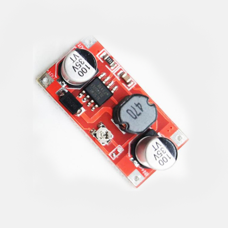
XL6007 IC as a DC-DC boost converter, focusing on its use in robotics. It includes technical details, applications, design considerations, and practical guidance. The XL6007 is a versatile, low-cost switching regulator ideal for stepping up voltages in battery-powered systems.
Overview and History
- Description: The XL6007 is a monolithic integrated circuit (IC) developed by XLSEMI (a Chinese semiconductor firm) for DC-DC voltage boosting. It operates as a step-up regulator, converting lower input voltages to higher outputs using inductive switching.
- Release and Evolution: Introduced around 2010-2015, it’s a successor to earlier boost ICs like the LM2577 (from National Semiconductor/TI). It’s popular in hobbyist and industrial electronics due to its simplicity and affordability.
- Why Relevant to Robotics: Robotics often requires efficient power management for components like motors and sensors, where batteries provide low voltage (e.g., 3.7-7.4V from LiPo cells). Boost converters like XL6007 enable higher voltages (up to 35V) without wasting energy, making them essential for mobile, autonomous robots.
- Evidence: Datasheet from XLSEMI (available on their site or distributors like Mouser). Widely used in open-source projects (e.g., Arduino forums) for robotics applications.
Technical Specifications
- Input Voltage Range: 3.6V to 32V (typical for battery inputs like 1-4 LiPo cells).
- Output Voltage Range: Adjustable from 5V to 35V (via feedback resistor divider).
- Output Current: Up to 4A peak but continuously rated at 2-3A for reliability (depends on input voltage and cooling).
- Efficiency: 85-94% at optimal loads (e.g., 90% at 12V output from 5V input), higher than linear regulators.
- Switching Frequency: ~400kHz (fixed), allowing small inductors (e.g., 22-100µH).
- Quiescent Current: Low (~100µA), minimizing standby drain in robotics.
- Protection Features: Built-in over-current protection, thermal shutdown (activates at ~150°C), and short-circuit protection.
- Pin Configuration (8-pin SOP package):
- VIN: Input voltage.
- GND: Ground.
- SW: Switching output (connects to inductor).
- FB: Feedback (voltage sense, typically 1.25V reference).
- EN: Enable (high for on, low for off; can be PWM-controlled).
- COMP: Compensation (for stability, often tied to GND via capacitor).
- VDD: Internal supply (usually connected to VIN via diode).
- NC: Not connected.
- Operating Temperature: -40°C to 85°C, suitable for outdoor robotics.
How It Works (Internal Operation)
- Principle: Uses a buck-boost topology with an external inductor, diode, and capacitor. The IC controls a MOSFET to charge the inductor from the input, then discharges it to the output, stepping up voltage.
- Cycle:
- MOSFET on: Inductor charges from VIN.
- MOSFET off: Inductor discharges through diode to output capacitor, boosting voltage.
- Feedback Loop: FB pin compares output to 1.25V reference; adjusts duty cycle to maintain voltage.
- Evidence: Based on standard switching regulator theory (e.g., from “Power Electronics” by Mohan et al.). Oscilloscopes show ~400kHz PWM waveforms.
Applications in Robotics
- Motor Powering: Boost battery voltage to 12-24V for DC motors, servos, or stepper drivers (e.g., in wheeled robots or robotic arms).
- Sensor Integration: Supply higher voltages for sensors like ultrasonic rangefinders, IMU modules, or LiDAR (e.g., YDLIDAR G2 at 5-12V).
- Microcontroller Support: Step up to 5V or 12V for boards like Arduino or Raspberry Pi in power-constrained setups.
Specific Examples:
- Drone Propulsion: Boost 7.4V LiPo to 12V for ESCs (Electronic Speed Controllers).
- Autonomous Rover: Provide 24V for motor controllers while using a 12V battery pack.
- POV Display Robot: Boost for LED arrays in spinning displays, as in your earlier Arduino code.
- Integration with Systems: Often used with buck converters for bidirectional power (e.g., in ROS-based robots for SLAM with LiDAR).
Design and Usage Guide
Component Selection:
- Inductor: 22-100µH, rated for 3-5A (e.g., toroidal for low EMI).
- Diode: Schottky (e.g., 1N5819) for low forward voltage drop.
- Capacitors: 10-100µF electrolytic on input/output; 0.1µF ceramic for decoupling.
- Resistor Divider: For FB pin, e.g., R1=10kΩ, R2=3.3kΩ for ~12V output (Vout = 1.25 * (1 + R1/R2)).
Circuit Diagram (Simplified):
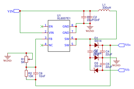
- VIN → Inductor → SW pin → Diode → Output Capacitor → Load.
- FB connected via divider to output.
- EN to microcontroller for control.
Control with Microcontrollers:
- Use PWM on EN pin for variable output (e.g., Arduino analog Write for dimming LEDs or adjusting motor voltage).
Testing and Calibration: Use a multimeter to measure output; oscilloscope for ripple (<100mV ideal). Adjust divider resistors for precision.
Comparisons to Alternatives
- Vs. LM2577: XL6007 is more efficient and compact but less robust for very high currents (>3A).
- Vs. MT3608 Module: MT3608 is a ready-made board using XL6007; easier for beginners but less customizable.
- Vs. Buck Converters: Boost steps up (e.g., 5V→12V); buck steps down (12V→5V). Use both for full power management.
- When to Choose XL6007: For low-cost, high efficiency boosting robotics; avoid very low inputs <3.6V) or high step-up ratios.
Pros and Cons
Advantages:
- High efficiency saves battery life in mobile robots.
- Adjustable and compact (fits small PCBs).
- Low component count; easy prototyping.
Disadvantages:
- EMI noise: may interfere with sensors—add LC filters.
- Efficiency drops at light loads or high ratios (e.g., 5V→30V).
- Requires external components; not fully integrated like some modern ICs (e.g., TPS61088).
Troubleshooting and Safety
- Common Issues: Output oscillation (add compensation capacitor); overheating (use heat sink); low efficiency (check inductor saturation).
- Safety: Fuse input (e.g., 5A); monitor temperature; avoid short circuits. In robotics, ensure polarity to prevent damage.