1.Introduction
Rover is a sophisticated open-source firmware, specially designed for autopilots in ground and water vehicles. This firmware supports not only conventional 3 or 4 wheel configurations, but also extends to boats, sailboats, balance bots, and walking robots. This versatile system can run missions autonomously, which can be defined via mission planning software or manually pre-recorded by the driver.
This guide will take you through the complete setup and first-time run of an ArduRover with a three-wheeled chassis, including a Pixhawk flight controller, ESP8266 Wi-Fi telemetry, and other essential components. By the end of this guide, your rover will be ready for manual and autonomous operation.
2. Required Components
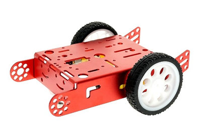
- 3-Wheeled Chassis (two driven wheels, one caster wheel)
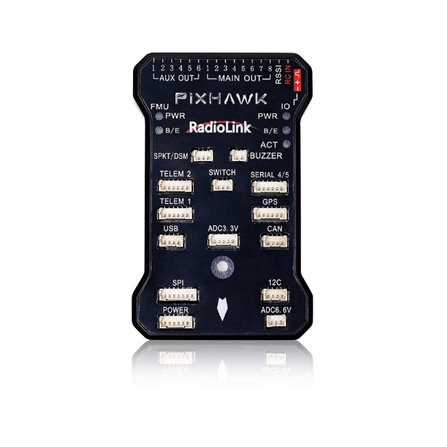
- Pixhawk Controller
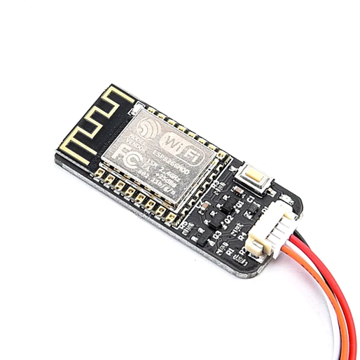
- ESP8266 Wi-Fi Telemetry Module
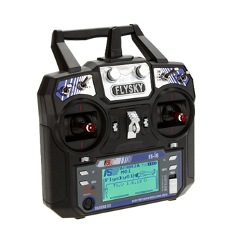
- 6-Channel Transmitter and Receiver
- L298N Motor Driver
- 2 Li-ion Batteries (7.4V)
- GPS Module
- 2 Brushed DC Motors (9V)
- Mission Planner (Ground Control Software)
3. Hardware Assembly
3.1 Chassis Assembly
- Begin by assembling the chassis, ensuring that the two driven wheels are securely mounted to the motor shafts.
- Attach the caster wheel at the front or rear, depending on your design preference.
3.2 Mounting the Pixhawk
- Securely mount the Pixhawk controller onto the chassis using standoffs or velcro.
- Ensure the Pixhawk is oriented correctly with the arrow pointing in the forward direction of the rover.
3.3 Motor and Motor Driver Setup
- Connect each brushed DC motor to the L298N motor driver.
- Attach the motor driver to the chassis near the motors.
3.4 Battery Setup
- Securely mount the two Li-ion batteries on the chassis using holder.
- Ensure the batteries are connected in series based to reach the desired voltage of 7v.
3.5 GPS Setup
- Mount the GPS module on the chassis with the help of included mount, preferably in an open area with a clear sky view.
- Change the connection to be compatible with Pixhawk.
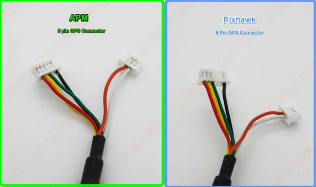
- Connect the GPS module to the Pixhawk.
3.6 ESP8266 Wi-Fi Telemetry Setup
- Connect the ESP8266 module to the Pixhawk telemetry port.
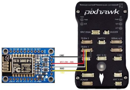
- Mount the ESP8266 module securely on the chassis.
4. Wiring and Connections
4.1 Pixhawk to L298N Motor Driver
- Connect the Pixhawk’s main output channels to the L298N motor driver input channels.
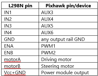
- Channel 1 and Channel 2 on the Pixhawk can be used for the ENA (left) and ENB(right) motors, respectively.
- AUX 3,4,5,6 will be used as IN1,IN2,IN3 and IN4 respectively.
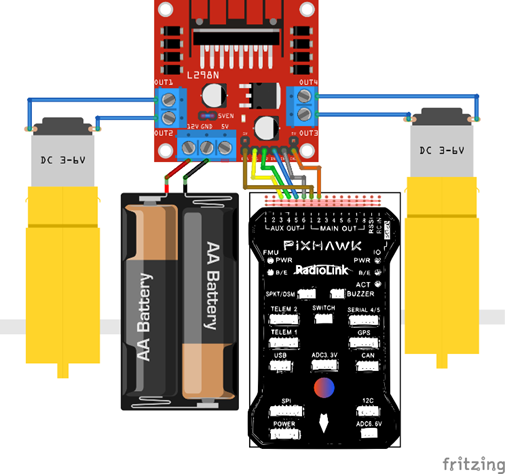
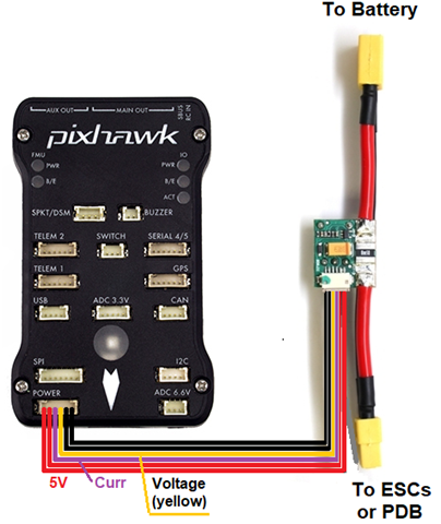
4.2 Power Distribution
- Connect the power module to the Pixhawk for regulated power.
- Ensure the L298N motor driver is powered directly from the Li-ion batteries.
5. Software Setup
5.1 Mission Planner Installation
- Download and install the Mission Planner software on your computer.
- Connect the Pixhawk to your computer via USB and launch Mission Planner.
5.2 Firmware Upload to Pixhawk
- In Mission Planner, navigate to the firmware section.
- Select “Rover” firmware and upload it to the Pixhawk.
6. Initial Configuration
6.1 Configuring Transmitter and Receiver
- Bind your 6-channel transmitter to the receiver.
- Connect the receiver to the Pixhawk’s RC input.
6.2 Setting Up ESP8266 Wi-Fi Telemetry
- After which the CH340 Driver was updated since the esp8266 was failing to be recognized. Later the Firmware firmware-esp01.bin for the esp8266 Wi-Fi telemetry was uploaded with esp8266 nodemcu upload tool ESP8266Flasher.exe
- If connected to Serial1/Telem1 these parameters should be set on the autopilot (if using another telemetry port, replace the “1” in the parameter name with the telemetry port’s number):
- SERIAL1_PROTOCOL = 2 (MAVLink2) or 1 (MAVLink1)
- SERIAL1_BAUD = 921 (921600 baud)
- If you have problems connecting, it may help to set BRD_SER1_RTSCTS = 0 to disable flow control although this is not normally necessary
- On your PC, open the Wi-Fi network connections screen and select the Wi-Fi access point (SSID “ArduPilot” with a lower-case password “ardupilot”) on the ground station, set the connection type to UDP and press “Connect”
- If all is well the ground station will connect, download parameters and the HUD should move as the vehicle is moved.
- Ensure it’s set up for MAVLink telemetry transmission.
6.3 Calibrating Sensors (Compass, Accelerometer, Radio)
- Use Mission Planner to calibrate the compass, accelerometer, and radio inputs.
- Follow on-screen instructions for each calibration step.
7. Rover Configuration in Mission Planner
7.1 Motor Output Setup
- Configure the motor outputs in Mission Planner.
- We will be using skid steering
- The wiring is already shown in the image above
- Ardupilot setup: Assuming calibration and other things are already completed. RC stick mode is set to 2 (left stick (up and down motion) controls throttle, right stick (left and right motion) controls steering).
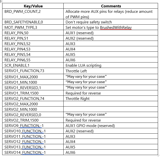
- BrushedWithRelay motor mode reserves the first relays (AUX1 and AUX2 in our case), so we must use other relay outputs for our purposes. In this case AUX3-AUX6 outputs will be used.
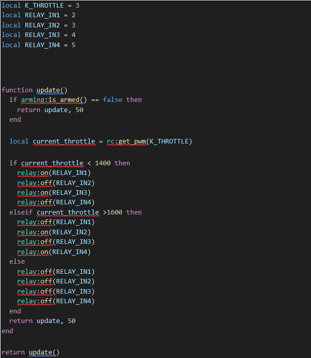
· In Mission Planner upload the set_rotation_dir.lua script to the scripts folder and reboot the Pixhawk.
set_rotation_dir.lua script
8. First-Time Run Checklist
8.1 Pre-Run Checks
- Verify all connections and ensure that components are securely mounted.
- Perform a range test with the transmitter and telemetry.
8.2 Initial Testing (Manual Mode)
- Switch the rover to manual mode.
- Test the rover’s movement with the transmitter to ensure correct motor operation.
9. Troubleshooting
- Common issues and fixes, such as motor jitter, GPS not locking, or telemetry disconnects.
10. Conclusion
- This ArduRover setup guide provides a comprehensive walkthrough for assembling and configuring a three-wheeled rover equipped with a Pixhawk flight controller, ESP8266 Wi-Fi telemetry, and L298N motor driver. The guide covers hardware assembly, including motor and GPS mounting, power distribution, and wiring connections for skid steering. It also details software setup through Mission Planner, firmware uploading, and sensor calibration, with specific configurations for Wi-Fi telemetry and motor control using a Lua script. The final steps include testing the rover in manual mode, verifying all connections, and addressing common troubleshooting issues, preparing the ArduRover for both manual and autonomous operations.