BLDC motors do not use brushes for commutation. Since the coils are static, there is no need of a mechanical commutator to energize the windings. Instead, the commutation is done electronically, usually via a microcontroller unit and semiconductor switches. Electronic commutation consists of a series of steps where current from an external drive circuitry is delivered to each phase coil in a controlled sequence, producing a proper motor rotation by magnetic interaction between rotor and stator. To achieve this in a three-phase motor, current flows into one of the windings, goes through a common node, and flows out from another, leaving a third one open circuit. That way, when a rotor pole is about to align with its electromagnetic counter-pole on the stator, this is turned off and the next phase turned on, which makes the rotating motion continuous.
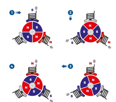
Electronic commutation by energized windings
The key part of this process is always keeping track of where the rotor is with respect to the stator so that the right phase can be excited at the right time. This is known as position feedback, which can be achieved with the aid of sensors or by reading the back-EMF produced in the windings. Electronic commutation can be sensored or sensorless depending on the means to estimate the rotor position.
Sensored Communication
The easiest and most common way to achieve electronic commutation is by using Hall-effect sensors for position feedback. These are located on the stator at 120° apart from each other in three-phase motors. Every time a rotor pole passes near a sensor, it will output a logic signal HIGH (for N-pole) or LOW (for S-pole), thus detecting the position of the rotor. These signals are then read by a microcontroller and sent to electronic switches in a driver circuit, allowing current to flow into the coils respectively and guaranteeing a proper commutation. Optical encoders are often coupled with Hall-effect sensors when a more precise position-tracking is needed. Using encoders not only offers better accuracy, but also speed and direction readings.
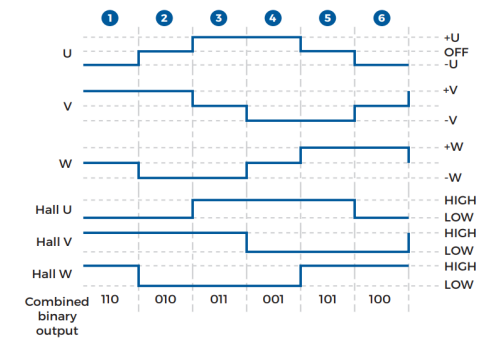
Phase excitation and Hall-sensor outputs
Sensorless commutation
As the rotor turns, voltage known as back-EMF is induced in the windings and opposes the supplied voltage. This resembles the behaviour of a generator, making this induced voltage proportional to the angular velocity of the rotor. Back-EMF is read from the non-energised coil in the commutation cycle, obtaining position and speed of the rotor at once. This technique is sometimes called trapezoidal commutation because of the back-EMF waveform.
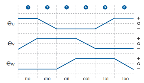
Phase excitation and respective back-EMF
Despite its high accuracy and cost-saving characteristics, sensorless commutation comes with some drawbacks. A minimum back-EMF is needed to properly execute commutation. This means that when the rotor is stationary, the motor is not able to start since no back-EMF is produced. Similarly, the induced back-EMF at low speeds might not satisfy the minimum speed required, resulting in a poor commutation. A common solution is to drive the motor through an initial open-loop stage where it is “freely” accelerated up to a minimum speed where the control algorithm can keep up with the commutation. Other solutions involve a pre-positioning step, initial position detection of the rotor with a microcontroller, or reading the line-to-line voltage difference to amplify the back-EMF.