If you’re looking to combine your love for gaming with a knack for tinkering, you’ve landed in the right place. Today, we’re pairing a game controller with an ESP32 using Bluetooth. That way, you can control all kinds of projects like robots, robot vehicles, animatronics, motorized props, or even cooler, a battle bot!
In order to get the ESP32 talking to my PS4 game controller, we’ll use an Arduino sketch to tap into the ESP32’s Bluetooth capabilities. This connection will later allow us to use the gamepad’s buttons and joysticks to control LEDs, motors, servos and more for our projects.
As for the Arduino code itself, there are a variety of Arduino IDE libraries that make it easy to connect your game controller to an ESP32 using Bluetooth. Some libraries are specific to certain game controllers, while others are more universal and allow you to connect a variety of controllers. The one we’re going to be using is Bluepad32. It supports most, if not all, modern Bluetooth game controllers, mice and keyboards. Not sure if you’re game controller is compatible? Check out the current list of Bluepad32-compatible controllers as well as what features are supported in the docs.
Setting up the Arduino IDE
Fire up your Arduino IDE! Once that blank sketch comes up, there are two …I call them pre-setup steps …that we’re going to have to go through. This means you can’t just scroll to the bottom of this ESP32 game controller tutorial and simply copy and paste the code!
It won’t work without first completing these steps:
1. Install ESP32 & Bluepad32 Board Managers
The Arduino IDE doesn’t come with support for ESP32 boards by default like for the rest of the Arduino microcontroller product line. But we can easily add it by installing board managers for both the ESP32 and Bluepad32. We can do this with just a few clicks right in the Arduino IDE!
Go to File => Preferences (Win) or Arduino IDE => Preferences (Mac)
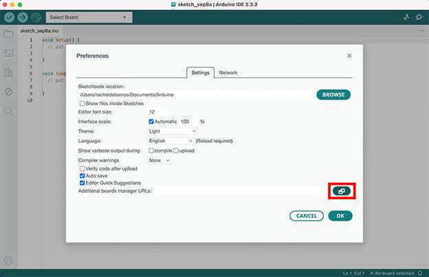
In the Preferences popup window, look for Additional Board Manager URLs towards the bottom. Just to the right of the text field is a button to expand that option. You’ll see a larger text field where you’ll be copy and pasting these 2 urls:
- ESP32 Boards Manager: https://raw.githubusercontent.com/espressif/arduino-esp32/gh-pages/package_esp32_index.json
- Bluepad32 Boards Manager: https://raw.githubusercontent.com/ricardoquesada/esp32-arduino-lib-builder/master/bluepad32_files/package_esp32_bluepad32_index.json
Be sure to copy and paste each url into its own line. The first one is for installing the boards manager for the ESP32 and this second one right below that is for installing the Bluepad 32 boards manager.
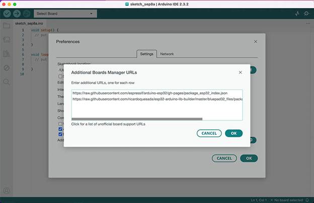
Click OK to close the Additional Boards Manager URLs expanded view. And then click OK again to close the Preferences popup window.
2. Add ESP32 & Bluepad32 Board Packages
With the two new boards managers installed, let’s now add the actual boards. Just a few more clicks and we’re there!
Go to Tools => Board => Boards Manager
In the text box at the top of the left column, start typing in esp32 and you’ll see some board packages come up below.
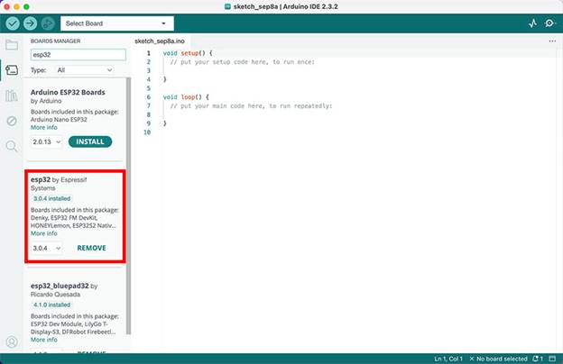
The one you want is called esp32 by Espressif Systems.
Click Install. It only takes a few moments for the installation to complete.
I already have it installed so my button appears as REMOVE.
After that, let’s do the Bluepad32 boards package. Back in the text box above, just continue adding bluepad32 and you’ll see esp32_bluepad32 by Ricardo Quesada come up.
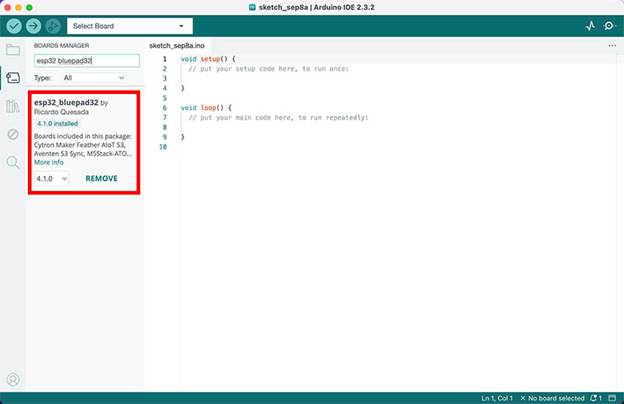
Click Install and wait a bit for the installation to finish up.
That’s it – our two pre-setup steps are done! All we have left to do is to select the board we’re using and the port that the ESP32 is plugged into.
Select the Correct ESP32 Development Board and Port
The Bluepad32 library comes with a few useful examples to help get us started, but in order to access them, we have to tell the Arduino IDE exactly what ESP32 development board we’re working with.
There’s a nearly endless variety of these development boards out there and the best way to find out exactly which one you have is to thoroughly read your ESP32 product listing and documentation.
I’m using this 30-pin ESP-WROOM-32 ESP-32S which is widely available and inexpensive.
Go to Tools => Board => esp32_bluepad32
You’ll be presented with a huge list of ESP32 development boards to choose from! In my case, I selected the DOIT ESP32 DEVKIT V1.
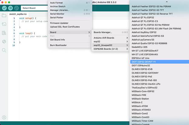
If you’re still not sure what development board you have, try this option first because it’s a really popular board. If you bought yours on places like Amazon or another inexpensive outlet, this is probably the one you have.
After that, let’s select our port.
Go to Tools => Port
Mine happens to be COM6. If you’re not sure what port to select, try unplugging other devices from your computer’s USB ports so that all you have left still plugged in is the ESP32. The port that still shows up in the Port menu is your ESP32 port!
Alright, all the boring stuff is done!
Bluepad32 Controller Example Sketch
Before we can start controlling motors, servos and more with our game controller, we first have to figure out how the buttons and joysticks are handled by the Bluepad32 library.
And thanks to one of the built-in example sketches, we can do this without typing a single line of code!
Go to File => Examples => Bluepad32_ESP32 => Controller
If you are a total beginner this Arduino sketch can seem pretty overwhelming. But the good news is that there’s only three main sections that we have to worry about:
1. Reading Game Controller Values
Scrolling down the example sketch, look for this code block called void dumpGamepad(ControllerPtr ctl) starting around line 44:
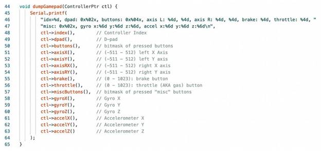
This block of code prints to the Serial Monitor all the values that your game controller buttons and joysticks output when they are pressed or moved around. That way, we can assign functions to these values like turning on LEDs with a button press, or accelerating motors and moving servos with a joystick.
Because this Arduino library supports so many different kinds of control devices, not all of this information will apply to my PS4 game controller. The ones we want to pay attention to for your typical gamepad is:
- ctl->dpad(): Values for the D-pad buttons
- ctl->buttons(): Values for all the other buttons including trigger
- ctl->axisX(): Left joystick values when you move it left and right (X axis)
- ctl->axisY(): Left joystick values when you move it up and down (Y axis)
- ctl->axisRX(): Right joystick values when you move it left and right (X axis)
- ctl->axisRY(): Right joystick values when you move it up and down (Y axis)
2. Processing Gamepad Actions
Continue scrolling down the Controller example sketch so we can take a look at the second notable section. Right around line 128, you should see the void processGamepad(ControllerPtr ctl) code block:
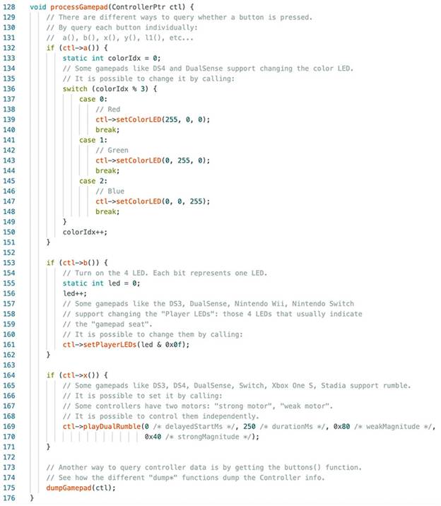
This section is where you’d normally put all the code to activate components on your project using the game controller. There are three examples in here for us to test out, some of which may or may not be compatible with your particular game controller:
- ctl->a(): If you press the “a” button on your gamepad, it will toggle between three light bar colors on your controller – red, green and blue. My PS4 controller doesn’t have an “a” button, so we’ll have to see which button this corresponds to once we upload this sketch.
- ctl->b(): If you press the “b” button, it allows you to select your “player seat” or “player color”. Normally, this is set when a player pushes the center PS4 button.
- ctl->x(): If you press the “x” button, then it will activate the rumble feature if your gamepad supports it. Keep in mind that the “x” button in the code may not correspond to the X button on your game controller.
There are a few different ways to specify actions for buttons with the Bluepad32 library and it just comes down to personal preference. I’m going to show you how I go about determining which button is which after we upload this Controller example.
3. Setting Up Components
The final code block that you have to pay attention to, and this is going to take some scrolling, is the setup loop.
The void setup() is a familiar part of every Arduino sketch but I wanted to point it out because it appears at the very bottom of the Controller example and is easy to miss! It’s around line 247:
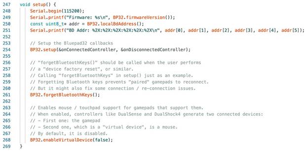
Many electronic components need certain attributes to be included in this section in order for them to work later on in the code. This can be setting up pinModes, initializing components on pins, or any other functionality that only needs to be executed one time. Simply leave the existing code in there and just add to it for your project.
How to Pair Your Game Controller to the ESP32
Let’s upload this code as is and see what happens!
Once the upload process is complete (which takes longer on ESP32 boards than Arduinos), pop open the Serial Monitor. Before you can pair your game controller, reset the ESP32 board by pressing the tiny EN button on it.
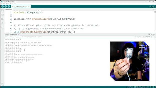
This causes some information about your Bluetooth connection to appear on the Serial Monitor. And now you can pair your game controller.
As soon as the pairing is successful, you’ll see all kinds of numbers corresponding to button presses scrolling up the Serial Monitor.