- Constraints allow you to control the relative position of sketch geometry in Fusion 360. If you look at the constraint icons in the sketch menu, you’ll see that sketch constraints use geometric expressions, except for “Fix/Unfix.”
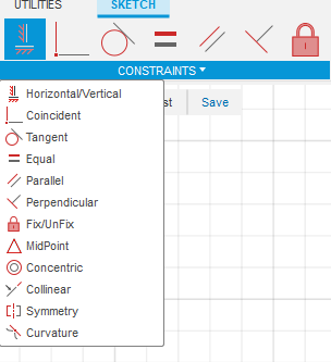
- These sketch constraints will help us maintain predictable behaviors when we update our sketch’s dimensions. You’ll want to use sketch constraints to maintain the shape of your sketch, so your sketch stays 100% predictable. Applying constraints and dimensions correctly will allow you to always know what will change within the given sketch.
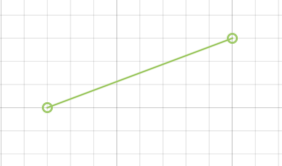
- Starting at the top of our constraints list, you’ll find the “Horizontal/Vertical” constraint. This constraint forces a line to snap horizontally or vertically, whichever orientation is the closest.
- The “horizontal/vertical” constraint is also commonly used to make points line up with one another.
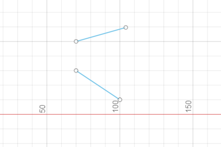
- Second on the list is the “Coincident” constraint. Coincident forces the two selected sketch entities to touch.
- To add a Coincident Constraint, we can select a point, line, or curve to join them together.
- We select one point on each line on the same side
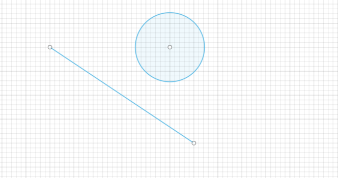
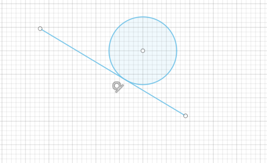
- The third constraint on our list is the “Tangent” constraint, which constrains a curve and another object so that they touch at a single point but never cross each other. The tangent constraint will help us create a smooth transition between a line and a curve.
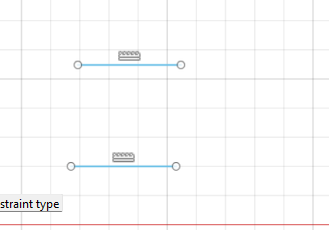
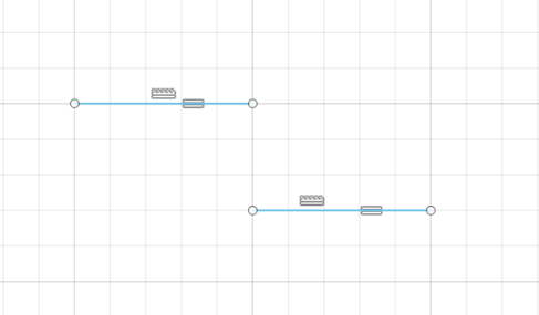
- Fourth on our list is the “Equal” constraint. This constraint forces two entities to remain equal in size. A common beginner mistake I see is when users apply the same sketch dimension to many sketch entities. Avoid doing so by first applying the Equal constraint. That allows us to only dimension one of the equal lines.
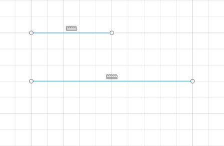
- The line which is selected second will be set to the dimension of the line that is selected second
- In this example the smaller line was selected first, hence the longer line was set to the short lines dimension
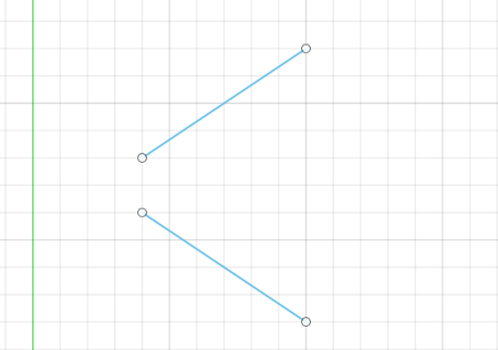
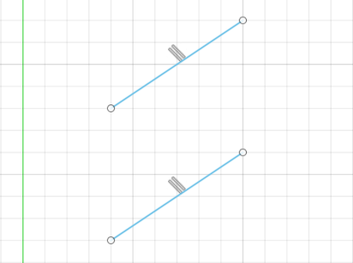
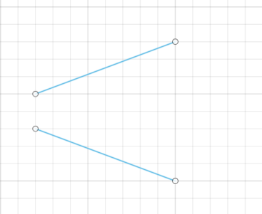
- The next constraint is the “Parallel” constraint, which makes any two lines parallel to each other. Select the parallel constraint to activate it and then select these two lines.
- We can now drag them around and they will always stay parallel to one another.
- Generally, you’ll use the Parallel constraint when a line is not in the horizontal or vertical direction.
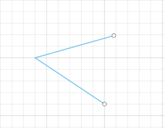
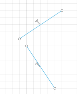
- The next constraint is the “Perpendicular” constraint. This constraint forces two lines to remain at a 90-degree angle to one another.
- An important thing to note is that the Perpendicular constraint does not have to be used on lines that are touching.
- Next, you’ll see the “Fix/Unfix” constraint. This command is unique in that it locks the size and location of a point or object.
- Fix/Unfix should be used sparingly. It works best on Spline geometry or other objects, such as Exploded Text, that are hard to fully constrain. Otherwise, the Fix constraint will prevent your sketch from adapting to changes in dimensions or other constraints.
- When applied, the “Fix” constraint will make the geometry green to indicate that it’s fixed.
- Now we select the two points and the line, so it is fully fixed
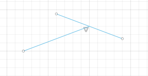
- Next is the “Midpoint” constraint, which is represented by a triangle. This constraint will be used frequently when sketching in Fusion 360 and helps us force the endpoint of a line to the center point of another line or arc.
- Select one line and one endpoint of the other line, the endpoint will be placed to the center of the selected line
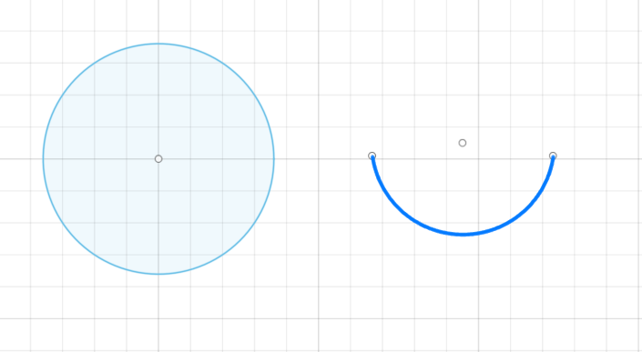
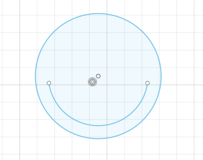
- The “Concentric” constraint helps us force circular sketch elements, such as circles and arcs, to share a common center point.
- For example, if we want this circle to share the same center point as the Arc, we can select both the Circle and the Arc. Notice both entities now share the same center point, which is represented by the concentric glyph.
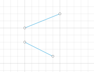
- Next on the list is the “Collinear” constraint, which forces two lines to share a single axis. They can be at any angle and do not have to be vertical or horizontal lines. The order in which you select the lines does matter if the lines are not horizontal or vertical.
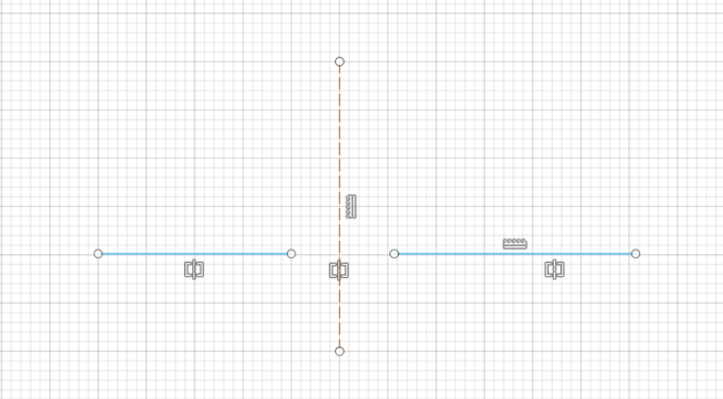
- Next up is the Symmetry Constraint. This constrains two or more objects, so they are symmetrical throughout the sketch.
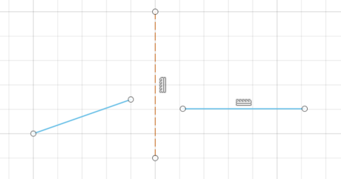
- The construction line will be used as the axis
- Select the two lines and then select the construction line as the axis, now the two lines will become symmetrical
- Finally, we have the “Curvature” constraint. This one is used less frequently but will come in handy when working on complex curvature.
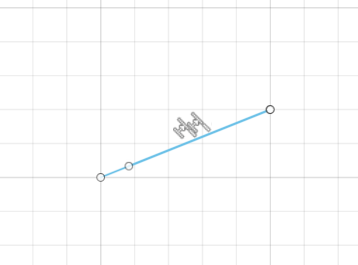
- The “Curvature” constraint constrains two or more objects to create a smooth continuous curvature between them.
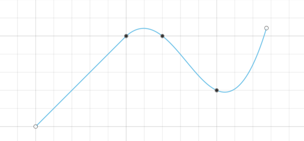
- Here we have a line with a spline connected to it
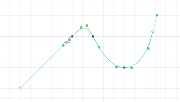
- We select the spline and the line after selecting symmetry function and click ok
- This creates a smooth continuous curvature