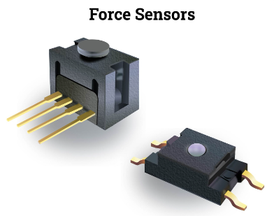
- Force sensors are transducers that transform mechanical input forces like weight, tension, compression, torque, strain, stress, or pressure into an electrical output signal whose value can be used to represent the force’s magnitude. To notify operators or act as inputs for controlling machinery and processes, the signals may be delivered to indicators, controllers, or computers.
- Although force sensors and force transducers are distinct from one another technically, the two phrases are most frequently used interchangeably. Power equipment, engineering machinery, various operating machines, and industrial automation systems all need force sensors now more than ever. Force sensors come in a variety of sizes and can be used to measure forces ranging from a few hundred grams to hundreds of tons.
- Bathroom scales, musical instruments, medical gadgets, autos to detect seat occupancy, and process control in industrial facilities are just a few of the many items and applications that use these devices. Force sensors will be discussed in this article, along with the typical types and their operational principles.
Force Sensor Principle of Operation
- The fundamental idea behind how force sensor’s function is that they react to the applied force and transform its value into a quantifiable value. Based on diverse sensing components, there are numerous types of force sensors on the market. Certain substances are referred to as force-sensing resistors which can alter their resistance ratings when they are subjected to a force.
- They typically include electrodes and a sensing material. The force imparted to an object can be measured with a force sensor. The applied force can be determined by measuring how much the resistance values of force-sensing resistors vary. Force-Sensing Resistors design most force sensors.
- A force-sensing resistor’s operation is based on the contact resistance property. In force-sensing resistors, a conductive polymer sheet changes resistance when force is predictably applied to its surface. This film is made up of a matrix of sub-micrometer-sized, electrically conducting, and non-conducting particles.
- The micro-sized particle touches the sensor electrodes when force is applied to the film’s surface, altering the resistance of the film. The degree of change brought about in the resistance values serves as a gauge for the force applied. In other words, it changes the electrical resistance, which may then be measured, from the mechanical force or pressure.
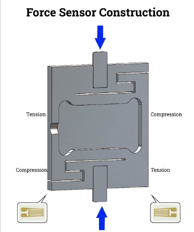
Construction and Design of Force Sensors
- Depending on the intended usage, force sensors can have a wide range of sizes and shapes. A force sensor consists of the following three fundamental parts. Finally, the circuit section is typically formed of enameled wire or PCB board, with the force-sensitive components typically composed of aluminum alloy, alloy steel, and stainless steel. The circuit is created by connecting these gauges across the sensing element; the conversion element is frequently a strain gauge made of a coil. To achieve the same outcomes, it is also possible to use a piezoelectric sensor that runs on a crystal.
- Analog voltage, analog current, analog frequency, switch or alarm, serial, and parallel are all possible force sensor outputs. The measuring circuit is made up of four gauges in the simplest designs. Up to thirty gauges can be included in a more intricate sensor’s measurement circuit. The force sensor’s sensitivity to detecting and tracking measurement deviation increases with the number of gauges it contains. The Wheatstone bridge equation, which was, typically governs the creation of these gauges and circuits.
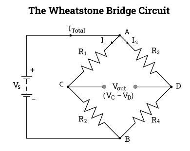
Wheatstone Bridge Circuit
- By using a changeable resistance and a straightforward mathematical calculation, the Wheatstone bridge diamond-shaped circuit can be used to precisely measure unknown resistance values or to calibrate measuring devices like sensors. It enables the measurement of extremely low resistance values down to the milli-Ohms (m) range by comparing an unknown resistance to that of known resistance to determine its value.
- With today’s operational amplifiers, we may utilize the Wheatstone Bridge Circuit to connect a variety of transducers and sensors to these amplifier circuits, which have a lot of applications. The Wheatstone bridge circuit consists of two straightforward series-parallel resistance configurations connected between a voltage supply terminal and ground, which, when balanced, produce zero voltage difference between the two parallel branches. It also consists of two input terminals, two output terminals, and four resistors arranged in the recognizable diamond pattern as depicted.
Micro-electromechanical Systems (MEMS) Fabrication
- On an insulator wafer, silicon nitride is first coated on both sides of the silicon. The front-side nitride is then etched; exposing most of the thin silicon on the front-side and leaving a nitride ring at the outer section of the front-side, using a photolithographically designed etch mask and a reactive-ion etcher.
- To protect the semiconducting silicon from the resistors that rest on the oxide, silicon oxide is then formed on the front side. Then, the nitride on the reverse is etched to create square windows that resemble the diaphragms. The silicon is then anisotropic ally etched in potassium hydroxide (KOH), with the nitride serving as an etch mask and the original oxide as an etch stop. The square silicon diaphragms hung over open cavities are released after the KOH etch. The open cavities are sealed with Pyrex wafers.
- Using hydrofluoric acid and a chromium-gold etch mask, channels are etched into the Pyrex wafer. The Pyrex wafer has a clean reversal face on the back and an engraved face on the front. After the SOI wafer and Pyrex wafer have been anodically connected, resistors are etched into a metal coating that has been deposited on the front-side by thermal evaporation.
- Finally, to waterproof and electrically insulate the resistors from the aqueous environment, a thin film of Parylene polymer is placed on the front-side. By using a die saw, it is possible to separate individual pressure-sensing cells or full pressure-sensing arrays from the bonded wafer pair before packaging them for testing. This is the sequence that must be used when fabricating. Metal needs to be patterned once it has been initially placed onto the wafer. Metal must be deposited after KOH-etching. KOH-etching must be followed by bonding. Between KOH-etching and bonding, metal patterning is not possible.
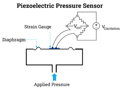
- We use a Wheatstone bridge circuit to detect and measure minute changes in resistance since the variations in the resistances are so small. Both the previously described piezoresistive pressure sensors and the strain-gauge pressure sensors employ this arrangement.
Types of Force Sensors
- In general, four types of force sensor technologies can be distinguished based on how the sensing element behaves. These force sensing methods, including capacitive, inductive, piezoelectric, and piezoresistive elements, successfully function in various environmental circumstances.
Inductive Force Sensor
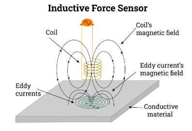
- An inductive sensor is a device that detects or measures items using the electromagnetic induction principle. A current will flow through a circuit that contains an inductor when the magnetic field changes through it, as opposed to when a current passes through an inductor and it creates a magnetic field.
- Metal objects that interact with a magnetic field can be found via this effect. An inductive sensor can function in damp or soiled environments because non-metallic objects, such as liquids or some types of dirt, do not interact with the magnetic field. Some inductive sensors alter their characteristics to measure a force, such as self-inductance, mutual inductance, or Eddy current creation.
- Low force readings and displacement measurements are best suited for inductive force sensors. With the development of a bi-directional inductive force sensor, it was possible to measure the force’s amplitude and direction in a plane. Eddy currents develop on the conductor’s surface because of the LC sensor’s AC magnetic field. The inductance of the inductive sensor is effectively reduced by eddy currents, which produce an opposite magnetic field. As a function of distance, the inductance changes.
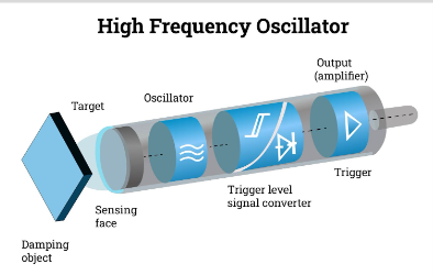
High-frequency Oscillation
- An electromagnetic field with a high frequency is produced by the oscillator and is emitted from the switch’s sensing face. Eddy currents are generated inside conductive metal when it meets this electromagnetic field, changing the oscillations’ amplitude. The outcome is a voltage change at the oscillator’s output, which modifies the trigger’s state and the output state.
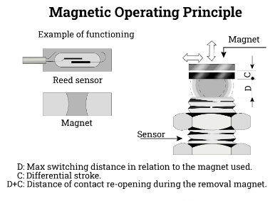
Magnetic Inductive Sensor
- A permanent magnet’s presence activates magnetic sensors. Reed contacts, whose thin plates are hermetically enclosed in a glass bulb with inert gas, form the foundation of their working theory. The thin plates bend and touch one other when a magnetic field is present, creating electrical contact. A specific substance that is particularly suited for low current or high inductive circuits has been applied to the plate’s surface.
- The benefits of magnetic sensors over conventional mechanical switches include Due to the hermetic glass bulb and inert gas, contacts are highly shielded from dust, oxidation, and corrosion; contacts are actuated by a magnetic field rather than mechanical parts. Long contact life is guaranteed by special surface treatment of contacts.
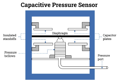
Capacitive Force Sensor
- Electrical capacitance measurements between conductors in a dielectric environment are used in capacitive sensing. Materials contain characteristics that a capacitive sensor may measure, such as the dielectric constant. The method works well with integrated circuits, which makes compact sensors possible. Applications for capacitive sensors include determining pressure, distance, thickness, proximity, and touch.
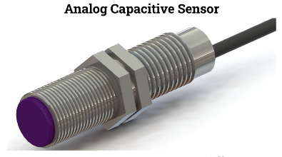
Analog Capacitive Sensor
- The analog capacitive sensor simply functions like ordinary capacitive sensors, but depending on how it is used, it offers various advantages. Comparing analog capacitive sensors to traditional capacitive proximity sensors, various advantages can be seen. They work effectively in a variety of settings, including those involving material selection, product thickness monitoring, concentration variation, and proximity sensing.
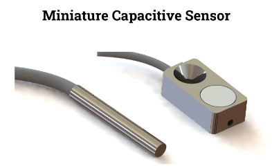
Miniature Capacitive Sensor
- The shape of this kind of capacitive sensor allows it to fit in even the smallest spaces. These sensors function like detectors used for task counting and are primarily used to monitor and regulate machine processes. Small sensor heads require an extra amplifier to fit in small places with the best precision. Therefore, the potentiometer on this external amplifier allows for altering sensitivity.
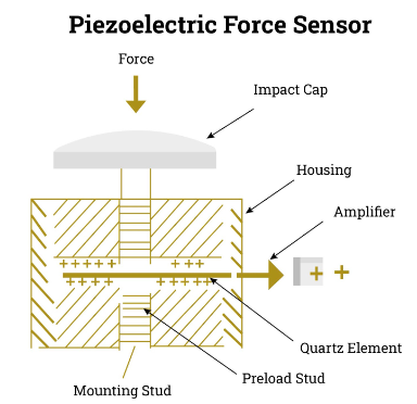
Piezoelectric Force Sensor
- A gadget that utilizes the piezoelectric effect is an example of a piezoelectric force sensor. Some materials produce an electric voltage when mechanical stress or forces are applied along specific planes.
Piezoresistive Force Sensor
- Force sensors of the resistive type vary their resistance and produce the necessary output while monitoring environmental factors including force, strain, and pressure. A force-sensing substance that can either be directly manufactured on the sensor or joined to the sensor is utilized in a strain gauge. A resistive force sensor detecting technique involves the resistive element being deformed against the substrate when an external force is applied to the sensor. The conductive material on the substrate comes into touch with the active area when air from the spacer aperture is forced through the air vent in the tail. As a result, conduction is feasible and the material’s resistance reduces. Force sensors of the resistive type vary their resistance and produce the necessary output while monitoring environmental factors including force, strain, and pressure.
Flexiforce Force Sensor Technology
Flexiforce touch force sensors are simple to integrate into force measuring applications where they are employed to gauge the force exerted between any two surfaces. The degree of bending can also be determined using flex sensors. Based on the bending strip theory, this sensor detects changes in resistance anytime the strip is bent. Any controller can be used to measure this. The sensor changes resistance when it bends, thus it functions similarly to a variable resistance. Flexiforce sensors are very thin and flexible printed circuits.
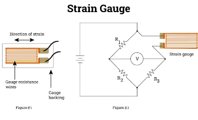
Strain Gauge
A strain gauge sensor uses elastic deformation of the strain gauge to convert an applied force to an electrical signal. Both static and dynamic forces may be present. Weight, acceleration, and pressure are a few examples. The strain gauge material’s internal deformation alters the gauge’s internal dimensions.
The wire lengthens and narrows when the force is parallel to the gauge’s thin wiring and tensile, much like tugging a rubber band. As a result, the gauge’s resistance rises. Like stretching, compressing reduces resistance by widening and shortening the wire. The amount of applied force directly relates to the change in the material’s electrical resistance in either direction.
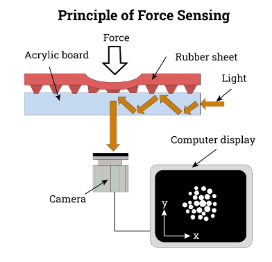
Optical Force Sensor
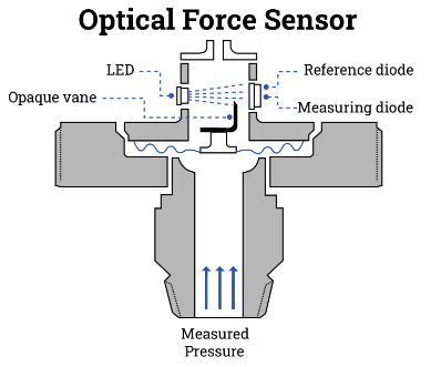
- The effect of pressure on light is how optical pressure sensors identify changes in pressure. The most basic form of this may be a mechanical device that dims the light when the pressure rises. The measurement of phase difference enables extremely accurate measurement of minute pressure changes in more sophisticated sensors.
- A rise in pressure will result in a progressive blockage of the light source in an intensity-based optical pressure sensor. The sensor then gauges the variation in received light. The pressure causes a diaphragm to move, and the associated opaque vane further dims the LED’s brightness. The photodiode detects the decrease in light intensity and directly measures pressure.
- A reference photodiode, which is never obstructed by the vane, is necessary for a straightforward optical pressure sensor like this one. This enables the sensor to compensate for variations in supply voltage and changes in the light output caused by other variables.
Applications of Force Sensors
- In industrial businesses, where force transducers are routinely employed to measure force for weight measurement or during production, force measurement is a major area of focus. For metering forces in industrial equipment and systems, such as in presses, assembly lines, or end-of-line inspections, force transducers are required.
- Scales are among the most typical applications for force sensors. Scales come in a wide variety of designs, including counting scales, bench scales, hopper scales, platform scales, truck scales, belt scales, and more. To provide accurate results when weighing different materials, force sensors are used.
- Weighing the contents of a heavy good or industrial vehicle while they are within the vehicle is known as onboard weighing. As a result, vehicles always carry the maximum amount of weight—neither too little, which would be inefficient, nor too much, which would be dangerous.
- A force sensor will be built inside the scales at the self-service checkout at the grocery store to weigh the items being scanned.
- Another force sensor use one may have seen is luggage scales at airports. Force sensors are used in the medical industry. They are used in applications such as fluid monitoring, MRI machines, dialysis machines, endoscopic surgery, and physical therapy equipment. Force sensors used in medical applications require medical authorization. In automobile traffic, force measurement is essential. For instance, force sensors are used in trucks. The axle load may therefore be precisely measured to enable effective and speedy monitoring.
- In cars, many force sensors are employed. For instance, force sensors near trailer couplings provide the opportunity to determine static data in connection to dynamic driving behavior on the road and to know the trailer’s weight. It implies that the vehicle’s control technology may respond more quickly and productively when the driver is at the wheel. In the railway sector, force sensors are applied in a variety of ways.
- They calculate the weights of the cargo, the passengers, or the tractive forces on the drawbar. All information gathered will be made accessible to guarantee secure and safe operation within the suggested limits. Force sensors are employed in the track system area in addition to on the railway.
- Aerospace applications that use force sensors include force feedback, flap detection, autopilot operations, and the flight recorder.
- Objects are tested to determine how much force is being applied to them using force sensors. An accident-related impact on a motorbike helmet, for instance.
- To produce domestic and worldwide comparability between measured values, reference measures are utilized. Here, systems are tested by metrological institutes all around the world using incredibly precise force transducers. Reference values are then provided by these institutes for both the domestic and global economies.
- Force transducers are frequently used on test benches to ensure that a desired material load can be properly controlled.