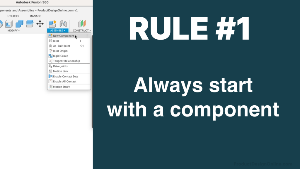
Rule #1 states that you should always start each new design with a new component.
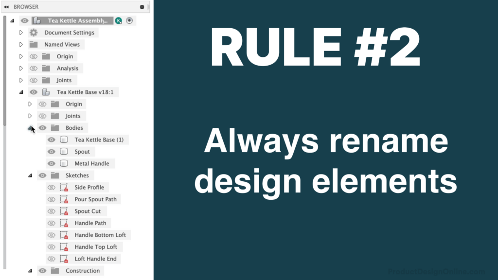
Rule #2 is to always rename all your components, sketches, and other design elements.
- In Fusion 360, a ‘Component’ represents a container for design elements. This includes Sketches, Construction Geometry, 3D Bodies, Joints, Origins, Canvases, and even other Components – but more on that later.
- Assemblies represent a collection of components that function as a single design. Any design that contains two or more components is considered an assembly. For example, our paperclip was an individual component, while our dog bowl was an assembly, as it includes a metal part and a rubber part.
- At a basic level, Components will help you keep your design organized in Fusion 360’s Browser. Components are required to leverage the full capabilities of Fusion 360. Components also allow you to define and manage Joints, or the mechanical relationships and motion between each part. Components are also required for parts list and many other manufacturing features.
- Every time you start a new design, your Fusion 360 file starts with a “top-level” component. This is also referred to as the “Root” component. Document Settings, Joints, and Named Views are always located within the topmost component.
- You’ll want to create a new component for every individual part in your assembly. Consider when parts are a different shape, material, and so on. Each of those should be its own component. Copies of the same part are something we’ll discuss later.
- You’ll find the ‘New Component’ feature by right-clicking on the Root component, in the toolbar, in the Assemble dropdown menu, or as the “Operation” in many of the modeling features within the Create menu.
- Upon creation, each component includes its own origin, coordinate system, and parametric timeline. This is a key differentiator of how Fusion 360 approaches multi-part models.
- When a component is active, the timeline will show only the features that pertain to that component. When the Root or Topmost component is active, your parametric timeline will display every feature in your design.
- It’s important to note that you should always be creating components before you start any design work. This ensures your sketches, construction geometry, and all the other design elements are placed in the desired container. This becomes crucial when wanting to copy and paste components or reuse components throughout patterns, mirrors, or even in other design files.
- With the component dialog still open, you can quickly create additional components by selecting ‘Repeat New Component’ from the right-click menu. This allows you to define the name and create a new component with the dialog remaining open. You’ll find this helpful to batch-create components before starting design work.
- Note that you’ll want to redefine the Parent component if you don’t want these to become nested into the previously activated component.
- If you forget to create a component before doing design work, your body will be placed at the top-level component, or whichever one was last active. You can create a component from a body by right-clicking on the body to select “Create Components from Bodies.”
- However, the tools and operations used to create the design remain in the top-level component and remain associated with its timeline, making it difficult to understand as you work on the design. This is why you should always create a component first, name it, and activate it before you start designing. Try to avoid using ‘Create Components from Bodies.’
- In the New Component dialog, you’ll see there are two types of components – Standard and Sheet Metal.
- Most of the time, you’ll use Standard components. Sheet Metal components are only used when designing specifically for Sheet Metal. The key difference is that a Sheet Metal Component contains a ‘sheet metal rule,’ which makes it easy for us to change the thickness of our sheet metal parts. This rule automatically updates the bend radius and other important sheet metal considerations.
- To understand the difference between ‘Internal’ and ‘External’ components, you need to understand the two main assembly types. Remember, an assembly simply represents a design file that contains two or more parts (components).
- Traditionally, programs like SolidWorks or Autodesk Inventor followed a ‘Bottom-up’ assembly approach. That means individual parts are all designed in their own design file and placed into a dedicated assembly file later.
- This traditional approach coincides with the concept of ‘External’ components. If we select this option, it will save our component as a separate design file. Note that we can define the location of the file.
- On the contrary, internal components follow the ‘Top-Down’ modeling approach, which represents creating all the Components within the context of a single design file.
- Fusion 360 is unique because it allows both modeling approaches, top-down and bottom-up, as well as some newer hybrid approaches. This concept can be confusing if you’re just starting with Fusion 360. As a great starting point, I’ll place the pros and cons of each modeling type on the accompanying web page.
- For now, just know that an internal component will live only in the active design file. An external component will appear in the active design file but is simultaneously saved as a separate design file.
- As an example, you’ll see this external component also appears as an individual design file in the Data Panel.
- Note that External components, which are commonly referred to as ‘Xref,’ are distinguished with a link icon in the Browser. The link icon lets you and others know that the component is pulled in from an external file.
- Unlike Internal components, External components cannot be activated and worked on within the context of the assembly file. You must go to the source design file to make design changes. However, when you save changes, you’ll see that the assembly file provides a warning that the design is out of date. We can right-click ‘Get Latest’ or select the warning icon in the applications bar. Doing so will pull in the latest design changes.
- External components are great if you plan to reuse the same part throughout several different assembly files. Changes can propagate to all of them, saving you valuable time.
- If at any time you need to break the reference to the original file, you can simply right-click and select ‘Break Link’. However, there is currently no way to relink an external component without reinserting the component altogether.
- Assembly files with 15 or even 20 different unique parts can be easily completed with the ‘Top-Down’ assembly approach. Remember that means we’ll only use ‘Internal Components,’ creating each of them within the context of a single design file.
- As you continue to design, it’s important to activate the desired component. This will preserve the parametric integrity by forcing all changes to happen inside the correct component.
- Right-click to select Activate, or hover over the Component to select the activate icon. This will allow you to edit any sketches or modeling commands, while non-active components become grayed out.
- Copying components is a great way to replicate parts. Right-click on the desired component and select copy. Then, we’ll want to make sure we right-click on the top-level component, before selecting “Paste.”
- The regular paste command will be an exact copy of the component and automatically inherit all changes made to the original.
- Use the ‘Paste New’ option if you want to copy a component without retaining the reference to the original. Paste New components are distinguished by a different numbering convention. I recommend renaming your ‘Paste New’ components immediately after creation. Pasted components will inherit the same name and cannot rename them individually.
- Remember, an Assembly is a collection of components that function as a single design. Any design that contains two or more components is considered an assembly.
- In the Browser, you can drag one component into another to control the hierarchy of the assembly. This keeps component-specific changes nested within the component’s timeline. It ensures your design is well organized and that it is easy for you and others to understand and interact with the timeline.
- Groups of nested components are often referred to as ‘Subassemblies.’
- Subassemblies not only help organize sections of your model, but they’ll also help you reuse multiple components at the same time. For example, in the Adirondack chair project from my Fusion 360 Masterclass, I taught students how to reuse this multi-component subassembly to create the other side.
- When working on large assemblies, you can isolate components to help focus on the active component without any other distractions.
- When complete, simply Un isolate to see the whole assembly.
- You may have also noticed that non-active components are transparent by default. This is to remind you which part is active, so you don’t accidentally work within the wrong component. However, this setting can be turned off in the Preferences if you’d rather everything be 100% opaque.
- If you’re not already convinced, here are some more reasons you should always be using components.
- Fusion 360’s components provide valuable properties such as mass, volume, and so on. This information is pulled in from the assigned physical property tool, which can only be applied to components. This is critical when working with Fusion 360’s simulation and manufacturing tools.
- Components also provide the Name, Number, and Description of parts when creating a parts list.
- Components must apply Joints, which is how you assemble two or more components together and define their degrees of motion.
- For example, this sawhorse file mimics reality thanks to the revolute joints applied to each hinge component. If components were not created during the design process, then all the parts would be floating in space and there’s not much we could do about it.
- Many of the 3rd-party add-ins also rely on components to pull in key data about your design.
- This leads us to the official Rules #1 and 2 from the Fusion 360 Forums